Semi-permeable discharge pipe and its discharging net

A drainage pipe and semi-permeable technology, applied in construction, infrastructure engineering and other directions, can solve problems such as unsatisfactory drainage effect, difficult to determine the location of the infiltration surface, and difficult to determine

Inactive Publication Date: 2008-02-06
INST OF ROCK & SOIL MECHANICS CHINESE ACAD OF SCI
View PDF0 Cites 11 Cited by
  • Summary
  • Abstract
  • Description
  • Claims
  • Application Information

AI Technical Summary

Problems solved by technology

[0004] 1. The traditional drainage pipe is a drainage measure and also a leaky pipeline; there is a gap between the drainage pipe and the drainage area, and some pore water will flow along the gap, and the drainage effect is not ideal;
[0005] 2. When the drainage area needs to be unstable seepage, the position of the wetting surface formed after the drainage pipe is inserted is not easy to determine, and the length of the permeable part of the drainage pipe wall (for example: the length of the screen hole and the length of the permeable pipe) is not easy to determine
If the length of the permeable part is too long, part of the water entering the drain will be transferred into the unsaturated area; if the length of the permeable part is too short, the drainage capacity is limited, and the drainage effect is also not good

Method used


Image

  • Semi-permeable discharge pipe and its discharging net

Examples


Embodiment Construction

[0030] Below in conjunction with accompanying drawing and embodiment the present invention is further described:

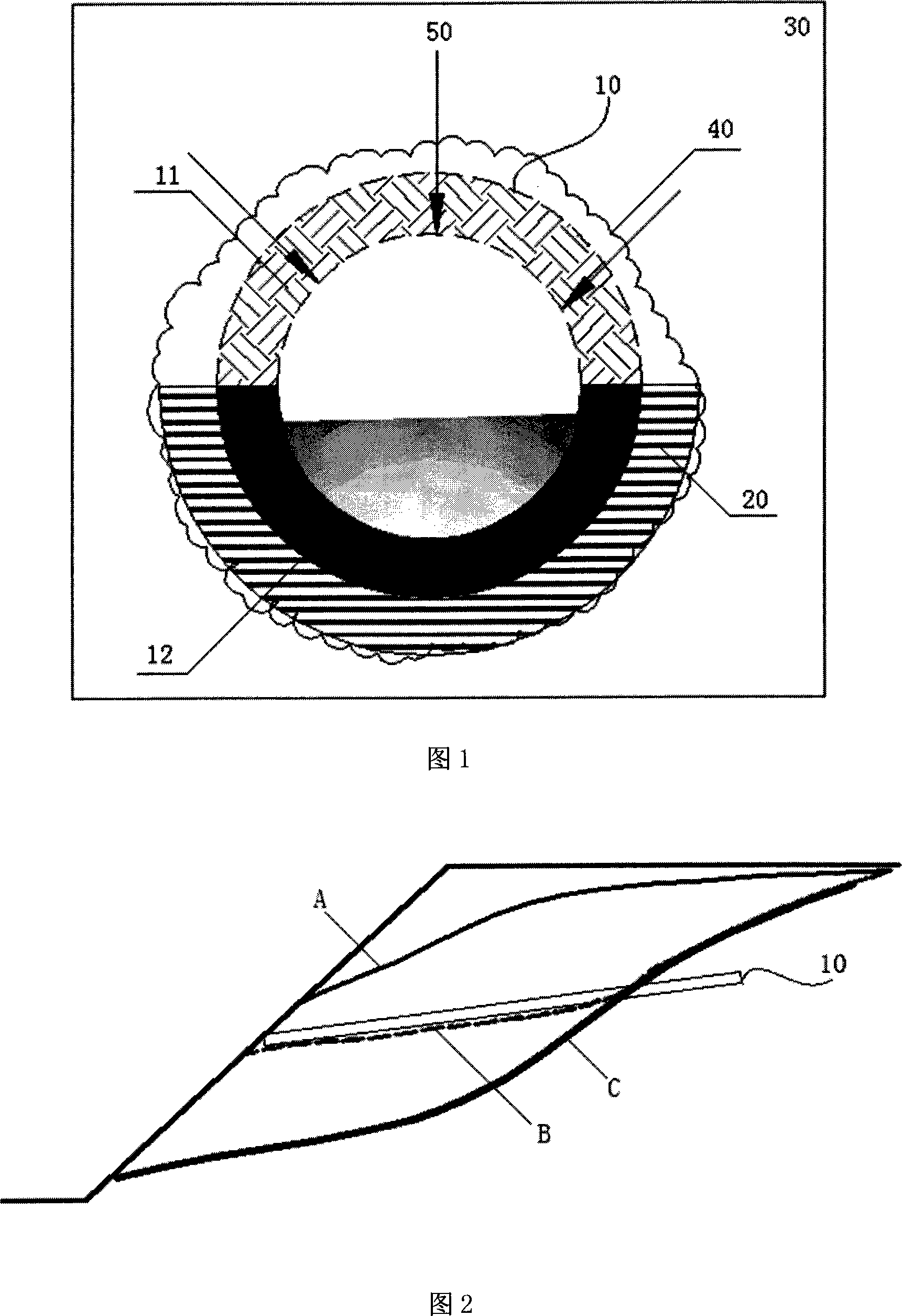
[0031] 1. Semi-permeable drainage pipe and its drainage network, as shown in Figure 1.

[0032] 1. Semi-permeable drainage pipe (10)

[0033] 1) The shape of the semi-permeable drainage pipe (10) can be any shape, such as: circular, elliptical, arbitrary polygonal, or irregular.

[0034] The semi-permeable drainage pipe (10) requires certain strength and rigidity to avoid damage during construction and use.

[0035] 2) Permeable upper half pipe (11)

[0036] Or for industrial permeable pipes, there are products on the market, such as: drainage boards, permeable pipes, flower pipes, grille pipes; or composed of permeable materials, including coarse-pore materials (average pore diameter> 0.01mm, such as: cement, gravel , Porous rubber), geogrid, geotextile.

[0037] 3) Watertight lower half pipe (12)

[0038] It should be able to withstand a certain load, apply...


PUM


Abstract

The present invention discloses a semi-permeable drainage pipe and a related drainage pipe network, and relates to a drainage pipe and a related drainage pipe network. A semi-permeable drainage pipe (10) is composed of an upper semi-pipe for permeability (11) and a lower semi-pipe for non-permeability (12). A structure of the drainage network based on the semi-permeable drainage pipe is described as follows: a drill hole (40) is arranged at a drainage zone (30), the semi-permeable drainage pipe (10) is arranged on the internal wall of the drill hole (40), and a water stop material (20) is arranged between the lower positions of the semi-permeable drainage pipe (10) and the drill hole (40). The present invention only drains water from the drainage zone (30) in a single direction, but does not transfer at other places except for the draining zone (30); reduces the location of the saturated surface of underground water; is applied to the civil engineering, the water conversancy, the transportation, the bridge, the mine, the municipal engineering, the agriculture, the horticulture and other drainage and precipitation fields.

Description

technical field [0001] The invention relates to a drainage pipe and its drainage network, in particular to a semi-permeable drainage pipe and its drainage network, which are suitable for various drainage and precipitation engineering fields such as civil engineering, water conservancy, transportation, bridges, mines, municipal administration, agriculture, and gardens. Background technique [0002] Traditional drainage pipes mainly use drainage technologies such as plastic pipes, steel pipes, drainage mattresses, drainage boards, and drainage prisms. The drainage pipes in these several technologies all face the problem that the leakage water is transmitted while the drainage pipe drains, and the water is easy to flow out from the gap between the outer wall of the drainage pipe and the wall of the borehole, and the drainage effect needs to be improved. [0003] Traditional drainpipes have the following disadvantages: [0004] 1. The traditional drainage pipe is a drainage mea...

Claims


Application Information

Patent Timeline
Patent Type & Authority Applications(China)
IPC IPC(8): E02D19/20
Inventor 李小春魏宁
Owner INST OF ROCK & SOIL MECHANICS CHINESE ACAD OF SCI
Why Eureka
Try Eureka