Hollow type plate illuminating device

A lighting device, hollow technology, applied in the direction of lighting device, lighting device parts, lighting and heating equipment, etc., can solve the problem of not being able to emit a large amount of white light, and achieve bright, light and uniform effects

Inactive Publication Date: 2008-02-06
HARISON TOSHIBA LIGHTING CORP
View PDF3 Cites 21 Cited by
  • Summary
  • Abstract
  • Description
  • Claims
  • Application Information

AI Technical Summary

Problems solved by technology

However, since this conventional backlight unit uses a small number of LEDs as a light source, it cannot emit a large amount of white light required for backlighting

Method used


Image

  • Hollow type plate illuminating device
  • Hollow type plate illuminating device
  • Hollow type plate illuminating device

Examples


no. 1 example

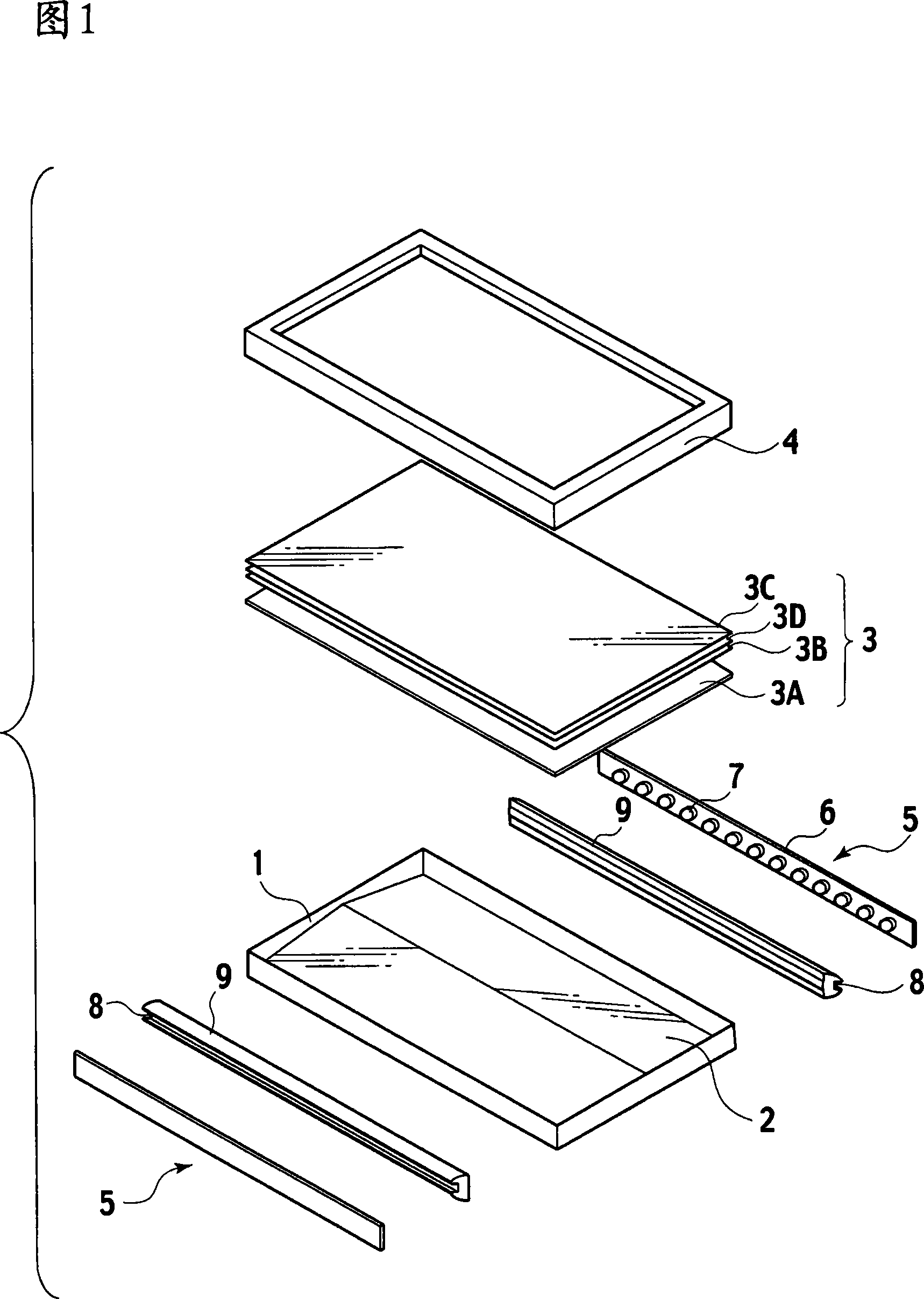
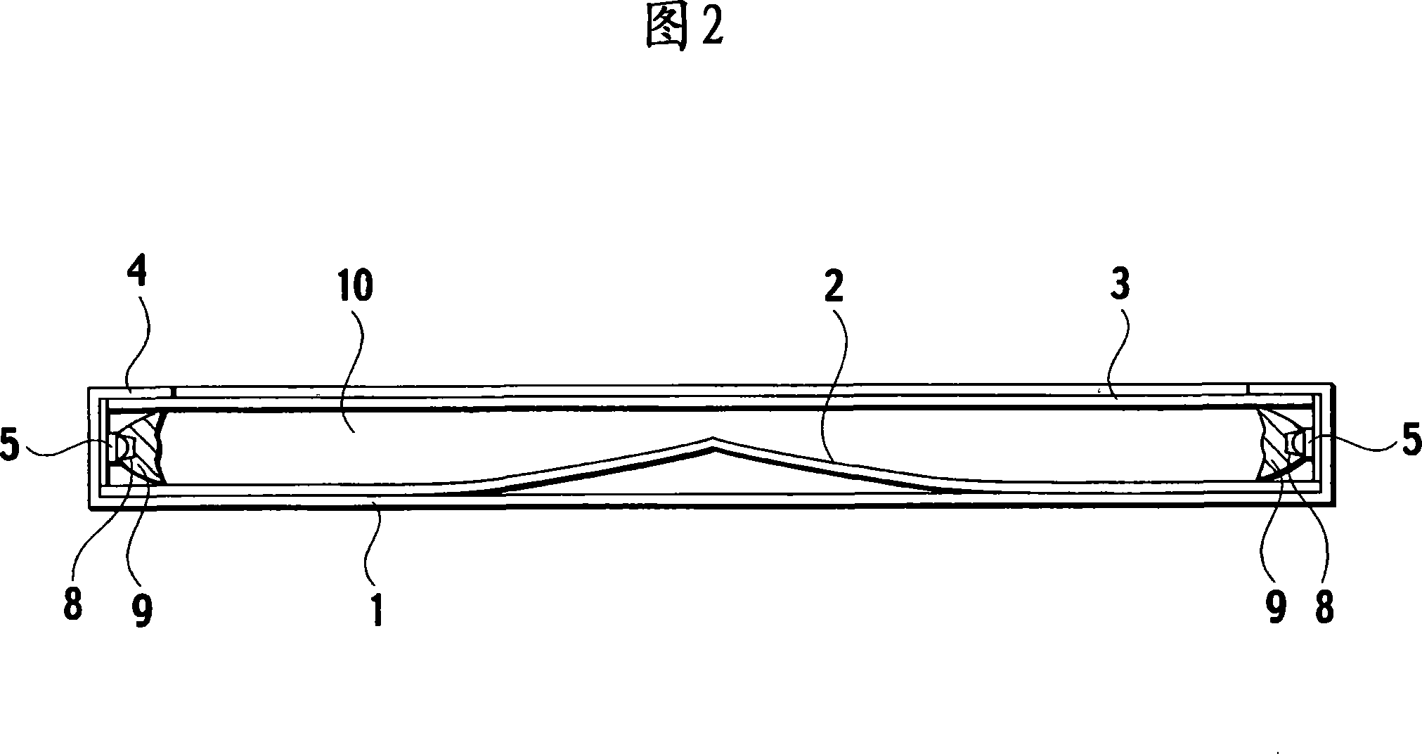
[0029] 1 and 2 show a hollow type flat panel lighting device according to a first embodiment of the present invention, which is used as a backlight unit of an LCD. The backlight unit has a housing 1 . At the bottom of the housing 1 a reflector 2 is arranged. The reflector 2 has a central ridge extending parallel to the sides of the housing 1 . The reflector 2 descends gradually from the ridge towards each side of the housing 1 . At the top of the housing 1 a light emitting surface part 3 is arranged. The light emitting surface part 3 is covered with a front frame 4 which is fixed to the housing 1 to form the backlight unit of the first embodiment. The space between the reflector 2 and the light-emitting surface part 3 in the housing 1 defines a light-guiding space 10 .

[0030] The reflector 2 is made of a substrate and a material with high reflectivity and scattering rate on the substrate, and the substrate is made of resin or metal. Highly reflective and scattering mate...

no. 2 example

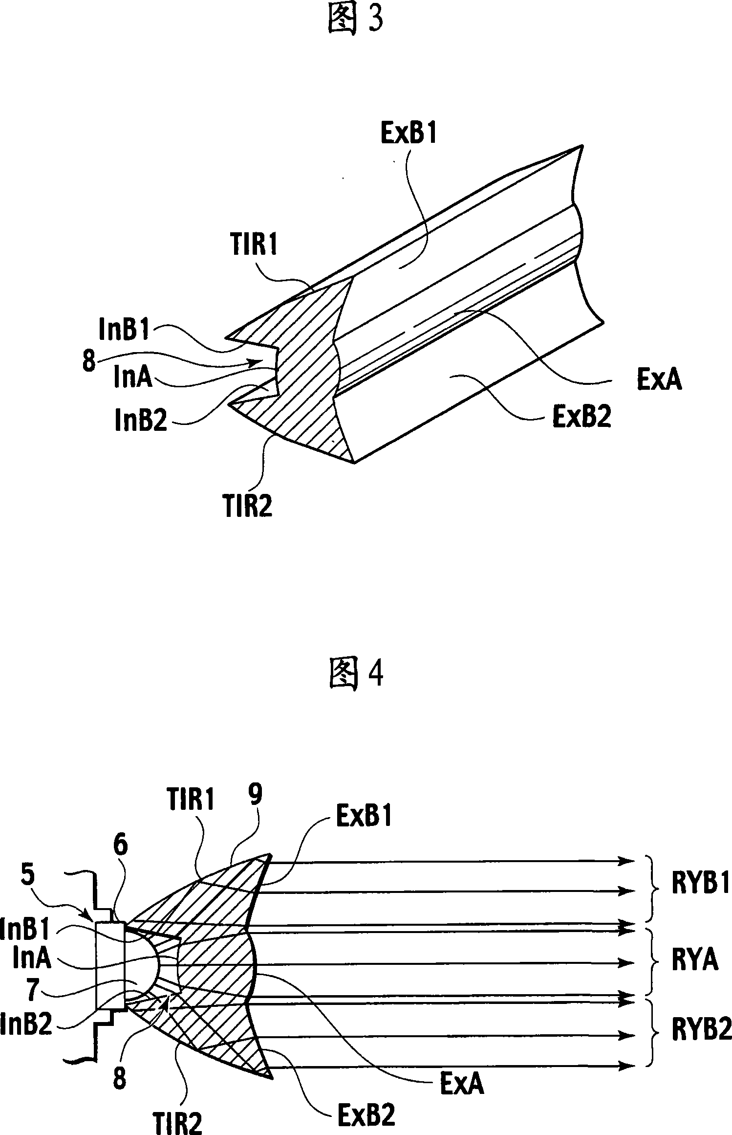
[0040] A backlight unit according to a second embodiment of the present invention will be described with reference to FIGS. 6 and 7 . The backlight unit of the second embodiment is characterized by a collimator 9A shown in FIGS. 6 and 7 . The collimator 9A has the same shape as the collimator 9 of the first embodiment shown in FIGS. 1 and 2 . The collimator 9A differs from the collimator 9 in that the groove 8A of the collimator 9A has incident surfaces InA, InB1 and InB2 each having a prism. Other parts of the backlight unit according to the second embodiment are the same as those of the backlight unit according to the first embodiment shown in FIGS. 1 and 2 .

[0041] In FIG. 7 , the light from the LEDs 7 on the LED bar 5 enters the interior of the collimator 9A through the incident surfaces InA, InB1 and InB2 of the groove 8A of the collimator 9A. The prisms on these entrance faces effectively scatter the incident light passing through the body of the collimator 9A. The ...

no. 3 example

[0044] A backlight unit according to a third embodiment of the present invention will be described with reference to FIGS. 8 and 9 . The backlight unit of the third embodiment is characterized by a collimator 9B shown in FIGS. 8 and 9 . The collimator 9B has the same shape as the collimator 9 of the first embodiment shown in FIGS. 1 and 2 . The collimator 9B differs from the collimator 9 in that each end of the groove 8B of the collimator 9B is terminated with an end face to form an end incident face InC. In addition, each end is provided with a total reflection end surface TIR3. Other parts of the backlight unit according to the third embodiment are the same as those of the backlight unit according to the first embodiment shown in FIGS. 1 and 2 .

[0045] In FIG. 9, the light from the LEDs 7 on the LED bar 5 is incident on the incident faces InA, InB1 and InB2 of the groove 8B of the collimator 9B. At the same time, light is incident on the incident surface InC at each end...


PUM


Abstract

Provided is a hollow flat illumination device used for a back light unit, comprising a housing, a reflector arranged at the bottom of the housing and an illuminous surface part arranged on top of the housing. A light guide space arranged between the reflector and the illuminous surface part. A LED light source is adjacent the light guide space. The LED light source is provided with a distribution board and an array of LED arranged on the distribution board. A collimated light tube at the illumination side of the LED light source to converge the light from the LED light source in the thickness direction of the housing and drive the light to diffuse parallel to the light axis of the LED array. The collimated light tube has the functionality portions (InA, InB1 and InB2) to refract the light from the LED array, guides the refracted light to go through the body of the collimated light tube and illuminates the light to the light guide space. The collimated light tube also has the functionality portions (TIR1 and TIR2), which wholly reflects the light entering into the collimated light tube and illuminates the light to the light guide space. The hollow flat illumination device is compacted and provides the bright and uniform light.

Description

technical field [0001] The present invention relates to a hollow flat panel lighting device having a surface for emitting light of uniform brightness, such as a backlight unit for an LCD (Liquid Crystal Display). Background technique [0002] Backlight units for LCDs are being replaced from using cold cathode discharge lamps to LEDs (Light Emitting Diodes). This is because LEDs do not contain harmful mercury, and thus are suitable as an environmentally friendly light source. In addition, recent LEDs have greatly improved luminous efficiency to significantly reduce power consumption. Backlight units with LEDs have been mainly used in small devices such as cellular phones and mobile terminals. However, these days, they are frequently used for large LCDs such as liquid crystal monitors and liquid crystal televisions of a size of 20 inches or more. [0003] A large LCD requires a bright backlight unit, and therefore, an edge-type backlight unit is not suitable for a large LCD...

Claims


Application Information

Patent Timeline
IPC IPC(8): F21V8/00F21V17/00F21V13/00G02F1/13357F21Y101/02F21Y105/00F21Y115/10G02F1/1335
Inventor 川崎要二木下顺一
Owner HARISON TOSHIBA LIGHTING CORP
Why Eureka
Try Eureka