Magnetic aligning device of aeolotropism adhesive bonding or sintered multipolar annular magnetic body

An anisotropic and bonding technology, applied in the manufacture of magnets, magnetic objects, inductors/transformers/magnets, etc., can solve the problems of complex structure of the magnetic field orientation device and low intensity of the orientation magnetic field, and achieve novel structural design and improve the orientation magnetic field. Strength, the effect of increasing strength

Active Publication Date: 2008-02-06
山西金开源实业有限公司
View PDF1 Cites 11 Cited by
  • Summary
  • Abstract
  • Description
  • Claims
  • Application Information

AI Technical Summary

Problems solved by technology

[0005] In order to solve the problem that the structure of the magnetic field orientation device of the existing ring magnet is complex and the intensity of the orientation magnetic field is low, so it is difficult to obtain the ideal orientation degree for the anisotropic NdFeB magnetic powder, the present invention provides a simple structure and high orientation Magnetic field orientation device for anisotropic bonded or sintered multipole ring magnets

Method used


Image

  • Magnetic aligning device of aeolotropism adhesive bonding or sintered multipolar annular magnetic body
  • Magnetic aligning device of aeolotropism adhesive bonding or sintered multipolar annular magnetic body
  • Magnetic aligning device of aeolotropism adhesive bonding or sintered multipolar annular magnetic body

Examples


Embodiment Construction

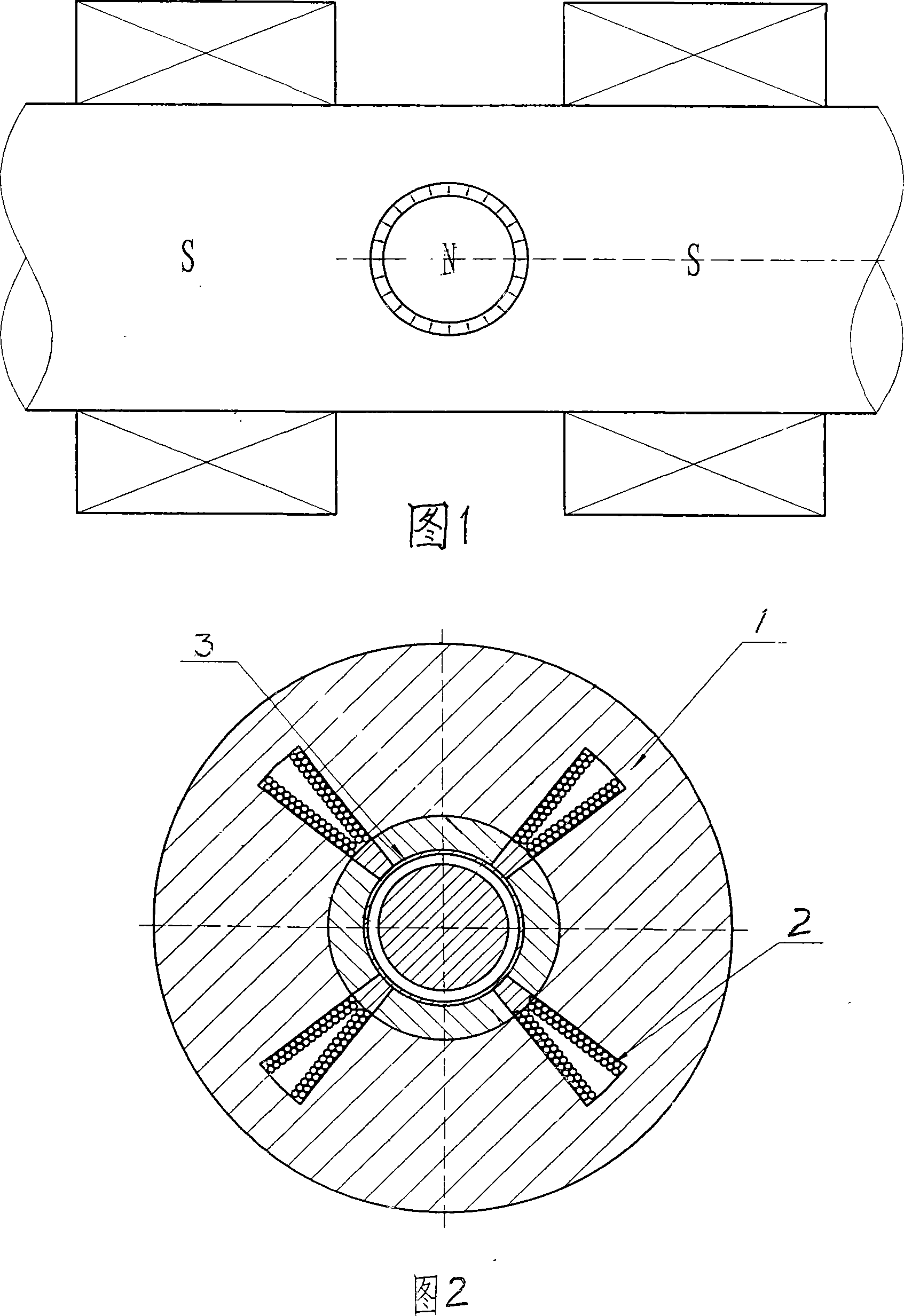
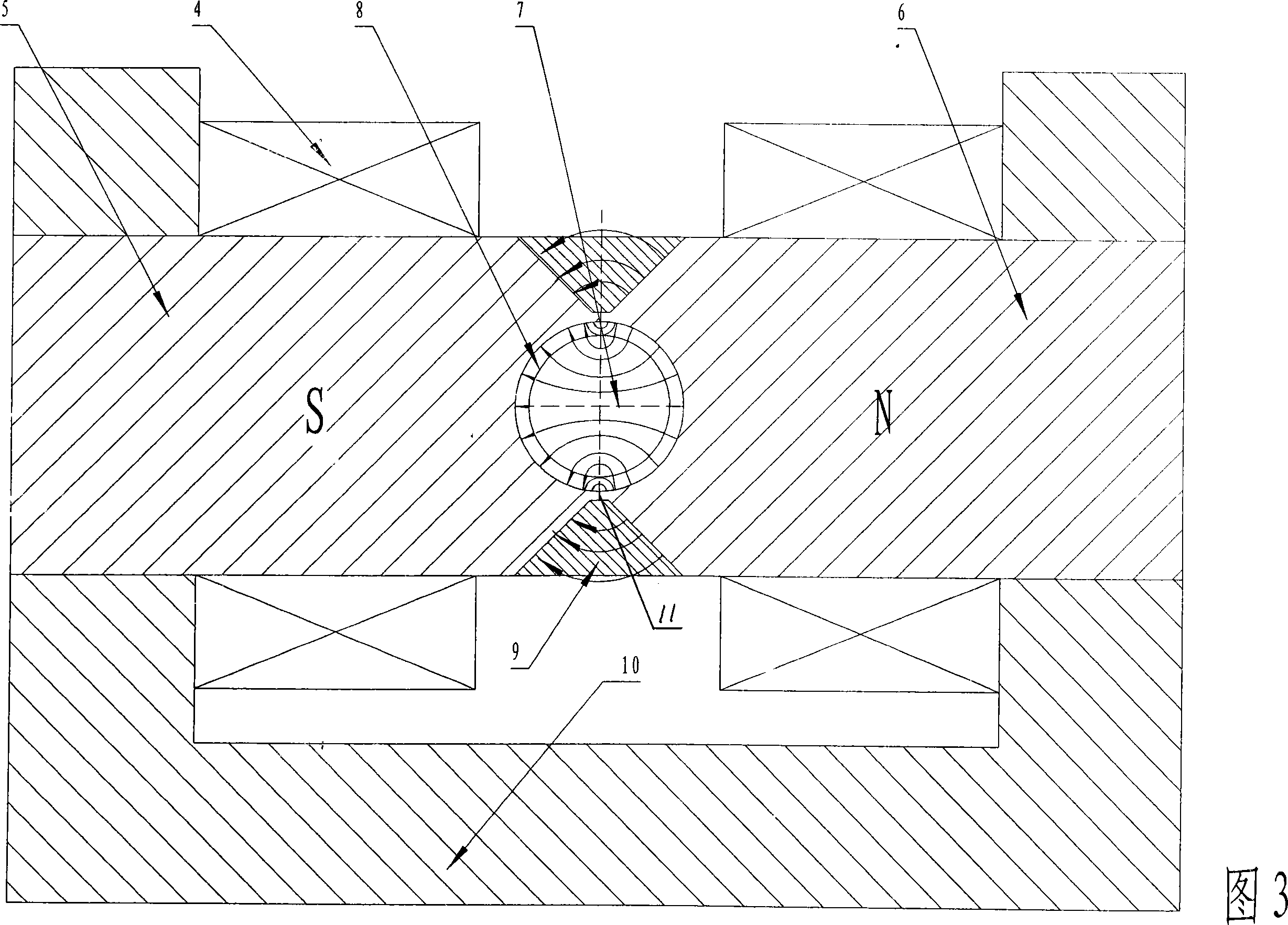
[0019] As shown in Figure 3. A magnetic field orientation device for anisotropically bonded or sintered multi-pole ring magnets, including an excitation coil 4, two magnetic poles 5, 6 and a cylindrical mold core 7 made of magnetically permeable materials, and the opposite polarity of the two magnetic poles Each head has a semi-cylindrical surface concentric with the mold core. The two magnetic pole heads are closed to form a circular cavity. A cylindrical core 7 is placed in the center of the circular cavity. The outer surface of the core is in line with the circular shape. The inner surface of the cavity forms an annular cavity 8 . In order to reduce the magnetic short circuit, the width of the contact surface 11 of the pole heads of the two magnetic poles is smaller than the thickness of the annular cavity. The two magnetic poles are fixed with a magnetic spacer 9 across the pole heads of the two magnetic poles, so that the two pole heads and the two magnetic spacer blocks...


PUM


Abstract

The present invention relates to a magnetic field orienting device of an anisotropy bonded magnet or a sintered magnet, in particular to a magnetic field orienting device of the anisotropy bonded magnet or a sintered multi-pole toroidal magnet. The present invention resolves the problems that the magnetic field device of an existing toroidal magnet has complex structure, low oriented magnetic intensity and difficult acquisition of the ideal degree of orientation for anisotropic NdFeB magnetic powder. The device comprises a field coil, two magnetic poles and a cylindrical mould core that is produced with magnetic conducting material, wherein, the pole heads of the two opposite magnetic poles are provided with a homocentric half cylinder respectively, the half cylinder is homocentric with the mould core. The two magnetic poles fold and form a round type cavity, and the mold core is arranged in the center of the round type cavity. The outer surface of the mould core and the inner face of the round type cavity form a toroidal cavity. The device has the advantages of simple structure and novel reasonable design; the magnetic intensity of the toroidal cavity can reach 1.5T to 2.5T in a non-transition area. Moreover, the anisotropic magnetic powder can obtain good degree of orientation. The orienting device can be used to produce multi-pole toroidal magnets.

Description

technical field [0001] The invention relates to a magnetic field orientation device for an anisotropic bonded magnet or a sintered magnet, in particular to a magnetic field orientation device for an anisotropic bonded or sintered multi-pole ring magnet. Background technique [0002] Manufacture of permanent magnet motor must have a ring magnet corresponding to its number of poles. As long as this magnet is made of anisotropic magnetic powder, it must use as strong a magnetic field as possible for the anisotropic magnetic powder during its forming process. Its most easily magnetized axis is oriented according to the required distribution. After forming, the distribution of the most easily magnetized axis is fixed, cured, and then magnetized to obtain the multi-pole ring magnet required by the permanent magnet motor. [0003] Shown in Fig. 1 is a kind of existing radiation magnetic field orientation device, the orientation device of this radiation magnetic field is a pole of t...

Claims


Application Information

Patent Timeline
Patent Type & Authority Applications(China)
IPC IPC(8): H01F41/02H01F7/00
Inventor 董中天
Owner 山西金开源实业有限公司
Why Eureka
Try Eureka