
Limited self-restricting reinforced concrete slab member in bending and manufacturing method thereof

A technology of reinforced concrete slabs and flexural members, which is applied in the directions of building members, floor slabs, building structures, etc., can solve the problems of slab cracks such as floor slabs or roof slabs, which are not well solved, and the bonding strength and structural rigidity are not enough. , There are no problems such as the formation of self-restraining concrete, and the effect of simple production method, low production cost and good crack width is achieved.

Inactive Publication Date: 2008-02-13
NINGBO INST OF TECH ZHEJIANG UNIV ZHEJIANG
View PDF0 Cites 1 Cited by
  • Summary
  • Abstract
  • Description
  • Claims
  • Application Information

AI Technical Summary

Problems solved by technology

[0006] However, the cold-rolled twisted reinforced concrete of the prior art still has the following deficiencies in practical application: since the cold-rolled twisted steel bars are evenly distributed in the unit area of ​​the floor slab or roof slab, the mutual contact between the cold-rolled twisted steel bars The distance between them is equal, and the cross-section rotation direction of all cold-rolled twisted steel bars is the same. The disadvantage is that the wedge columns formed by each cold-rolled twisted steel bar and concrete do not have strong attraction to each other, and the concrete wedge columns There is no mutual restraint, and no self-contained concrete is formed. Therefore, the bonding strength and structural rigidity of the reinforced concrete flexural members of the prior art are still insufficient, and its maximum crack width is difficult to control within the range allowed by the state. Its floor slab or The problem of cracks in roof panels and other panels is still not well resolved

Method used


Image

  • Limited self-restricting reinforced concrete slab member in bending and manufacturing method thereof
  • Limited self-restricting reinforced concrete slab member in bending and manufacturing method thereof
  • Limited self-restricting reinforced concrete slab member in bending and manufacturing method thereof

Examples


Embodiment Construction

[0031] The present invention will be described in further detail below in conjunction with the accompanying drawings and specific embodiments.

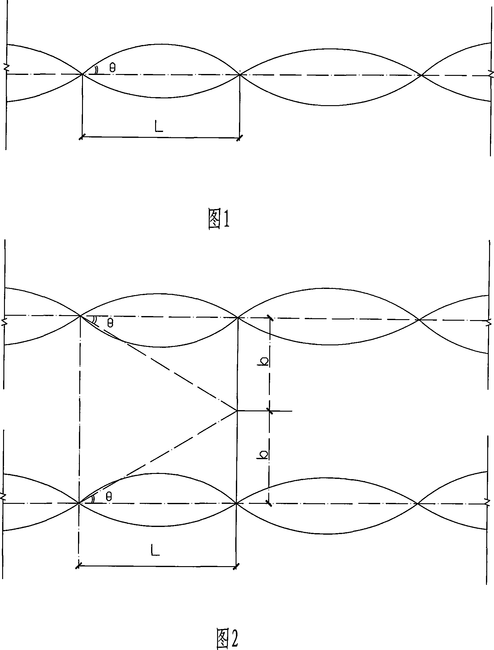
[0032] As shown in Figure 1, the spiral cold-rolled twisted steel bar used in the present invention is a cross-section such as approximately rectangular, square, circular, etc. formed by continuous cold rolling and cold twisting of smooth round steel bar raw materials. For special-shaped steel bars that undergo periodic helical changes along the axis of the steel bar, the distance of a periodic change in the section is called pitch L, and the helical angle is generally between 35° and 40°.

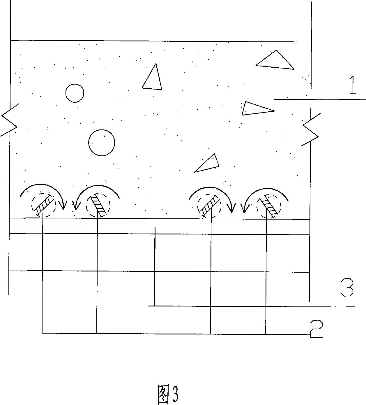
[0033] As shown in Figure 3, Figure 5, Figure 6, and Figure 7.

[0034] The present invention's limited self-constrained reinforced concrete slab-type flexural member includes concrete 1 and several stressed cold-rolled twisted steel bars 2 (that is, cold-rolled twisted steel bars are used as stressed steel bars) whose cross-section is spiral, and...


PUM


Abstract

The invention discloses a bent component for limited self-restraining steel bar concrete plate, which includes the concrete (1) and a plurality of stressed cold rolled and twisted steel bars (2) arranged in the concrete and with spiral cross sections, and a plurality of distribution steel bars (3) which are connected and spread vertically to the stressed cold rolled and twisted steel bars (2); the stressed cold rolled and twisted steel bars (2) are deployed in pairs; the spiral rotation angles of the two stressed cold rolled and twisted steel bars (2) in every pair are the same, but the spiral rotation directions are to the opposite. The making method includes making of the stressed cold rolled and twisted steel bars (2) and the distribution steel bars (3), making of installation templates, installing and binding of the stressed cold rolled and twisted steel bars (2) and the distribution steel bars (3), casting of the concrete, maintenance and mould removal of the cast steel bar concrete structure. The component can form the self-restraining concrete, to improve the structure rigidity and control the crack width, and so that the making technology becomes convenient.

Description

technical field [0001] The invention relates to a concrete member such as a floor panel and a roof panel for civil buildings and a manufacturing method thereof, in particular to a limited self-constrained reinforced concrete slab bending member and a manufacturing method thereof. Background technique [0002] In the field of civil engineering, concrete structures have the advantages of economy, simplicity, practicality, and easy access to materials, and are still widely used so far. [0003] Among them, the prestressed concrete structure uses high-strength steel bars or steel wires or fiber materials as the main tensile reinforcement and provides prestressing for the structure, which can effectively improve the structural properties such as stiffness and crack resistance of the structure. The field has been widely used, such as the application of nuclear reactor safety shields, etc., which have obvious technical, economic and social benefits, and have become a symbol of high...

Claims


Application Information

Patent Timeline
Patent Type & Authority Applications(China)
IPC IPC(8): E04B5/00
Inventor 吴佳雄
Owner NINGBO INST OF TECH ZHEJIANG UNIV ZHEJIANG
Learn More