Engine with decompression device

A decompression device, engine technology, applied in the direction of engine components, machine/engine, engine cooling, etc., to achieve the effect of suppressing increase, realizing miniaturization, and realizing the number of assembly processes

Active Publication Date: 2010-10-27
HONDA MOTOR CO LTD
View PDF5 Cites 2 Cited by
  • Summary
  • Abstract
  • Description
  • Claims
  • Application Information

AI Technical Summary

Problems solved by technology

[0004] However, in the above existing structure, since the decompression counterweight is arranged at the shaft end of the camshaft, there is a problem that the camshaft including the decompression device overall length increase
[0005] In addition, since the intermediate member is sandwiched between the shaft end of the decompression camshaft and the decompression counterweight, there is a problem that the number of parts of the decompression device increases

Method used


Image

  • Engine with decompression device
  • Engine with decompression device
  • Engine with decompression device

Examples


Embodiment 1

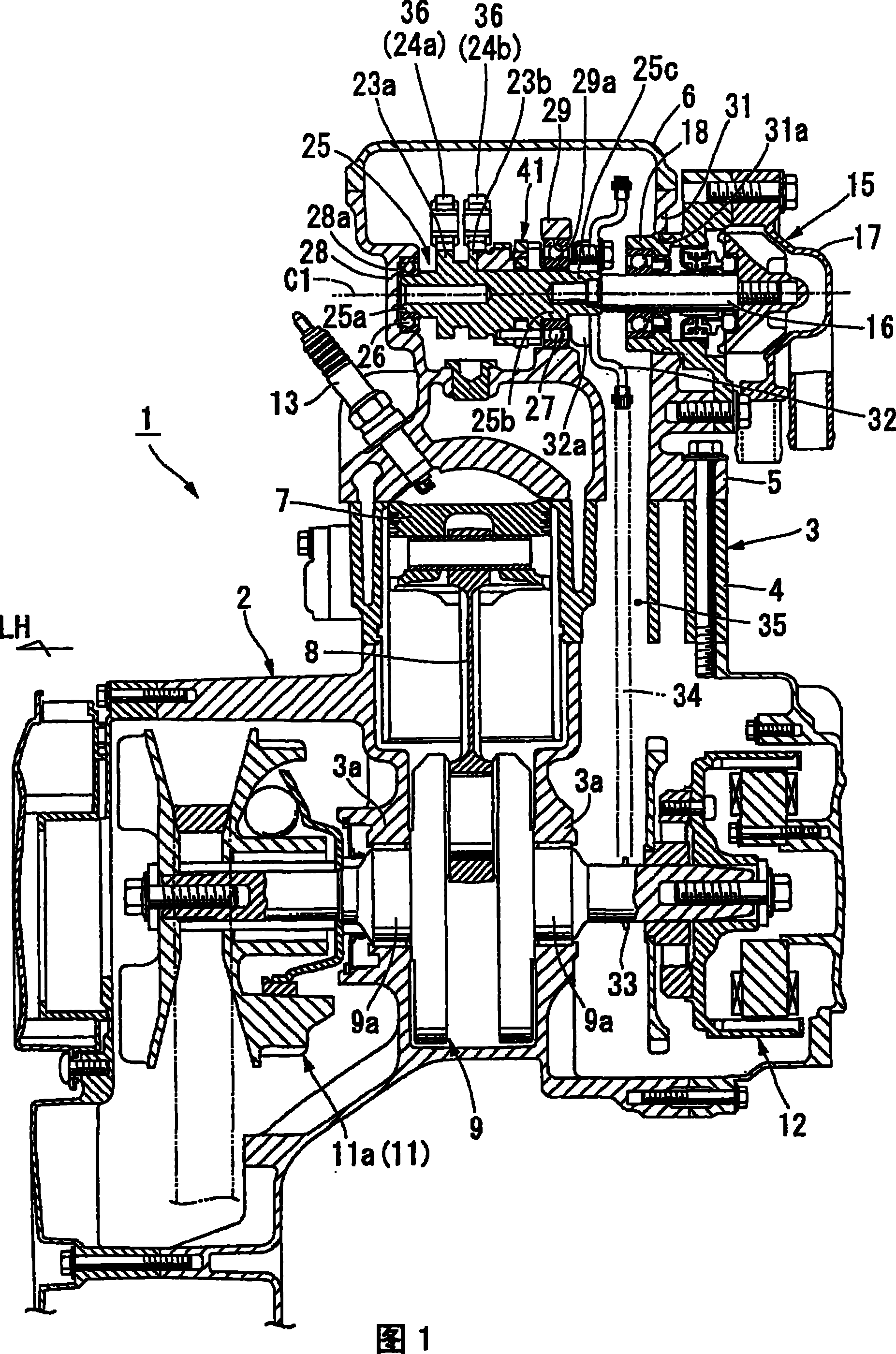
[0038] figure 1 The shown engine 1 is used, for example, as a prime mover of a vehicle such as a motorcycle, and is constituted by a water-cooled four-cycle single-cylinder engine.

[0039] The cylinder unit 3 protrudes from the crankcase 2 of the engine 1 . The cylinder unit 3 is mainly composed of a cylinder body 4 attached to the crankcase 2 , a cylinder head 5 attached to the front end of the cylinder body 4 , and a head cover 6 attached to the front end of the cylinder head 5 . Here, the arrow LH in the figure indicates the left side.

[0040] A piston 7 is reciprocally fitted inside the cylinder body 4 . Piston 7 is connected to crankshaft 9 via connecting rod 8 . Left and right journals 9 a of the crankshaft 9 are rotatably supported by left and right bearing portions 3 a of the crankcase 2 .

[0041] The rotational power of the crankshaft 9 is output via, for example, a belt-type continuously variable transmission mechanism 11 . Further, a drive pulley 11 a of th...

Embodiment 2

[0089] Next, regarding the second embodiment of the present invention, refer to Figure 8-12 Be explained.

[0090] The main difference between the engine 101 (decompression device 141) of this embodiment and the above-mentioned first embodiment is that the decompression counterweight 142 is provided with the above-mentioned locking mechanism on the side opposite to the counterweight part 142c sandwiching the rotating shaft 148. For the pin 54, the same reference numerals are assigned to the same parts as those in the above-mentioned embodiment, and the description thereof will be omitted.

[0091] Figure 8The camshaft 125 shown has an axis C1' along the left-right direction, and its right end (right journal 25b) is rotatably supported by a right bearing support portion of the right inner wall 29 of the cylinder head 5 via a right ball bearing 27. 29a, the left end portion (left journal 125a) is rotatably directly supported by the left journal support portion 128a inside th...


PUM


Abstract

To suppress the overall length of a camshaft including the length of a decompression device provided in an engine and also to suppress an increase in number of parts of the decompression device, an engine includes a decompression device having a decompression weight pivotably supported through a pivot shaft to a camshaft and adapted to be rotated at a predetermined angle by a centrifugal force generated during the rotation of the camshaft. A weight accommodating portion for pivotably accommodating the decompression weight is formed between the opposite end portions of the camshaft. The outer diameter of the decompression device mounted to the camshaft is smaller than that of a ball bearing. The decompression weight is directly engaged with one end of a decompression camshaft to thereby rotate the decompression camshaft.

Description

technical field [0001] The present invention relates to an engine provided with a decompression device (decompression device) for releasing compression pressure at the time of starting. Background technique [0002] Conventionally, the above-mentioned engine is provided with a camshaft and a decompression weight, the camshaft has an intake and exhaust cam between both ends, and supports the above-mentioned both ends on a camshaft support portion of the engine body, and the decompression weight The weight is rotatably supported on the camshaft via a rotating shaft, and rotates at a predetermined angle by the centrifugal force generated by the rotation of the camshaft (for example, refer to Patent Document 1). Arrange the decompression counterweight on the outer side of the supported part on the one end side of the camshaft, and extend the decompression cam shaft arranged near the exhaust cam to the above-mentioned one end side, and lock the shaft end and the decompression co...

Claims


Application Information

Patent Timeline
Patent Type & Authority Patents(China)
IPC IPC(8): F01L13/08F02N17/00F01P5/10F02N19/00F02N99/00
CPCF01L2820/035F02B75/16F01P5/04F01L2001/0535F01L13/085F01L2001/0476F02F7/0004F01L1/047F01L13/08F01P5/12
Inventor 山西辉英平山周二额田芳隆大河千春
Owner HONDA MOTOR CO LTD
Why Eureka
Try Eureka