A power generation device based on magnetic flow body

A magnetic fluid power generation and electrode technology, applied in electromechanical devices, electrical components, etc., can solve the problems of materials and manufacturing difficulties, and achieve the effects of fast startup, improved efficiency, and convenient load connection

Inactive Publication Date: 2008-02-13
HEFEI HUAQING DAAN ELECTRONICS SCI & TECH
View PDF0 Cites 9 Cited by
  • Summary
  • Abstract
  • Description
  • Claims
  • Application Information

AI Technical Summary

Problems solved by technology

[0006] (1) High temperature problem: Since the temperature in magnetic fluid power generation is generally 2000-3300K, this has caused many difficulties in the materials and production of combustion chambers, power generation channels, etc.
[0007] (2) The production of superconducting magnets: Since a strong magnetic field is required in magnet...

Method used


Image

  • A power generation device based on magnetic flow body

Examples


Embodiment Construction

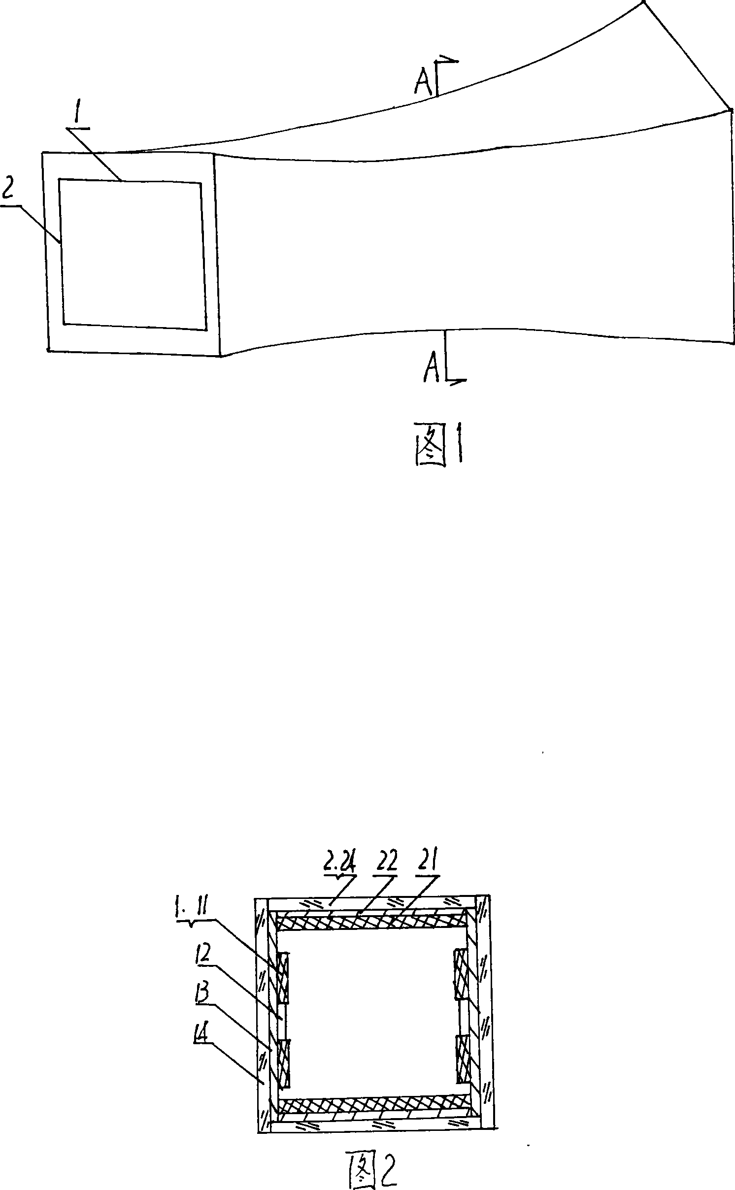
[0015] As shown in Figures 1 and 2, a magnetic fluid power generation device consists of two opposing electrode walls 1 and two opposing magnetic pole walls 2 with opposite polarities to form a box-shaped channel with a square cross-section. The channel is a linear longitudinal expansion channel, the inner surface of the channel entrance is 100mm×100mm, the inner surface of the outlet is 120mm×120mm, the wall thickness is 20mm, and the channel length is 400mm. The electrode wall is composed of an electrode 11, a copper plate 12 connected to the electrode and a glass fiber reinforced plastic 14 bonded to the copper plate from the inside to the outside. 24 electrodes are installed on both sides of the electrode wall. The electrode is in the shape of a square plate with a size of 18mm×18mm. The electrode material is graphite electrode, which does not need to be cooled, and the electrode voltage drop is small. A 2 mm thick boron nitride sheet 13 is embedded between adjacent elec...


PUM


Abstract

A magnetohydrodynamic generation device belongs to the technical field of generator, and is to provide a magnetohydrodynamic generation device having high generating efficiency and meeting requirement of automobile. According to the technical essential, a square cross section passage in box structure consists of two opposite electrode walls (1) and two opposite magnetic pole walls having inverse polar phases constitute; the passage is a linear vertical expansion passage, and is larger and larger from an entrance of the passage; the outlet section is larger than the section of the entrance; the electrode walls consist of poles (11), copperplates (12) connected with the poles, and fiberglass reinforced plastics (14) adhering to the copperplates from interior to exterior; the magnetic pole walls consist of neodymium iron boron sheets (21), steel plates (22) fixing the neodymium iron boron sheets and fiberglass reinforced plastics (24) adhering to the neodymium iron boron sheets. The utility model makes use of interaction between thermion gasses of automobile off-gas and the magnetic field, directly converts heat energy into electrical energy; the utility model both makes use of fuel energy source, but also is environmentally protective. In addition, the utility model has no moving parts, is started up quickly, outputs direct current and meets automobile utilization characteristics.

Description

Technical field: [0001] The invention relates to a power generation device, in particular to a magnetic fluid power generation device which utilizes automobile exhaust to generate power. Background technique: [0002] After Faraday discovered the law of electromagnetic induction, he had the idea of ​​using ocean currents to generate electricity through the earth's magnetic field. This is the earliest idea of ​​the principle of magnetic fluid power generation. However, in terms of research on magnetic fluid power generation technology, the former Soviet Union, the United States, Japan, China and other countries have conducted a lot of research. The United States was the first to conduct research on magnetic fluid power generation technology. In early 1940, Westinghouse Electric Company manufactured a large-scale Hall-type test generator. Due to insufficient understanding of the properties of ionized gases, this generator was unsuccessful. In 1959, Afcor Corporation built an ...

Claims


Application Information

Patent Timeline
IPC IPC(8): H02K44/08H02K44/10H02K44/12
Inventor 朱卫国刘万青
Owner HEFEI HUAQING DAAN ELECTRONICS SCI & TECH
Why Eureka
Try Eureka