Eureka AIR delivers breakthrough ideas for toughest innovation challenges, trusted by R&D personnel around the world.

Process for adjusting the angular position of the camshaft of a reciprocating internal combustion engine relative to the crankshaft

A technology of reciprocating pistons and camshafts, used in valve devices, mechanical equipment, engine components, etc., can solve problems such as non-adjustable phase, and achieve the effect of low fuel consumption and small harmful substance discharge

Active Publication Date: 2008-02-13
SCHAEFFLER TECH AG & CO KG
View PDF1 Cites 3 Cited by
  • Summary
  • Abstract
  • Description
  • Claims
  • Application Information

AI Technical Summary

Problems solved by technology

However, this only applies conditionally to the starting process of the internal combustion engine, since during the starting process there are still no measured values ​​regarding the phasing of the camshafts and therefore it is not possible to optimally adjust the phasing

Method used


Image

  • Process for adjusting the angular position of the camshaft of a reciprocating internal combustion engine relative to the crankshaft
  • Process for adjusting the angular position of the camshaft of a reciprocating internal combustion engine relative to the crankshaft
  • Process for adjusting the angular position of the camshaft of a reciprocating internal combustion engine relative to the crankshaft

Examples


Embodiment Construction

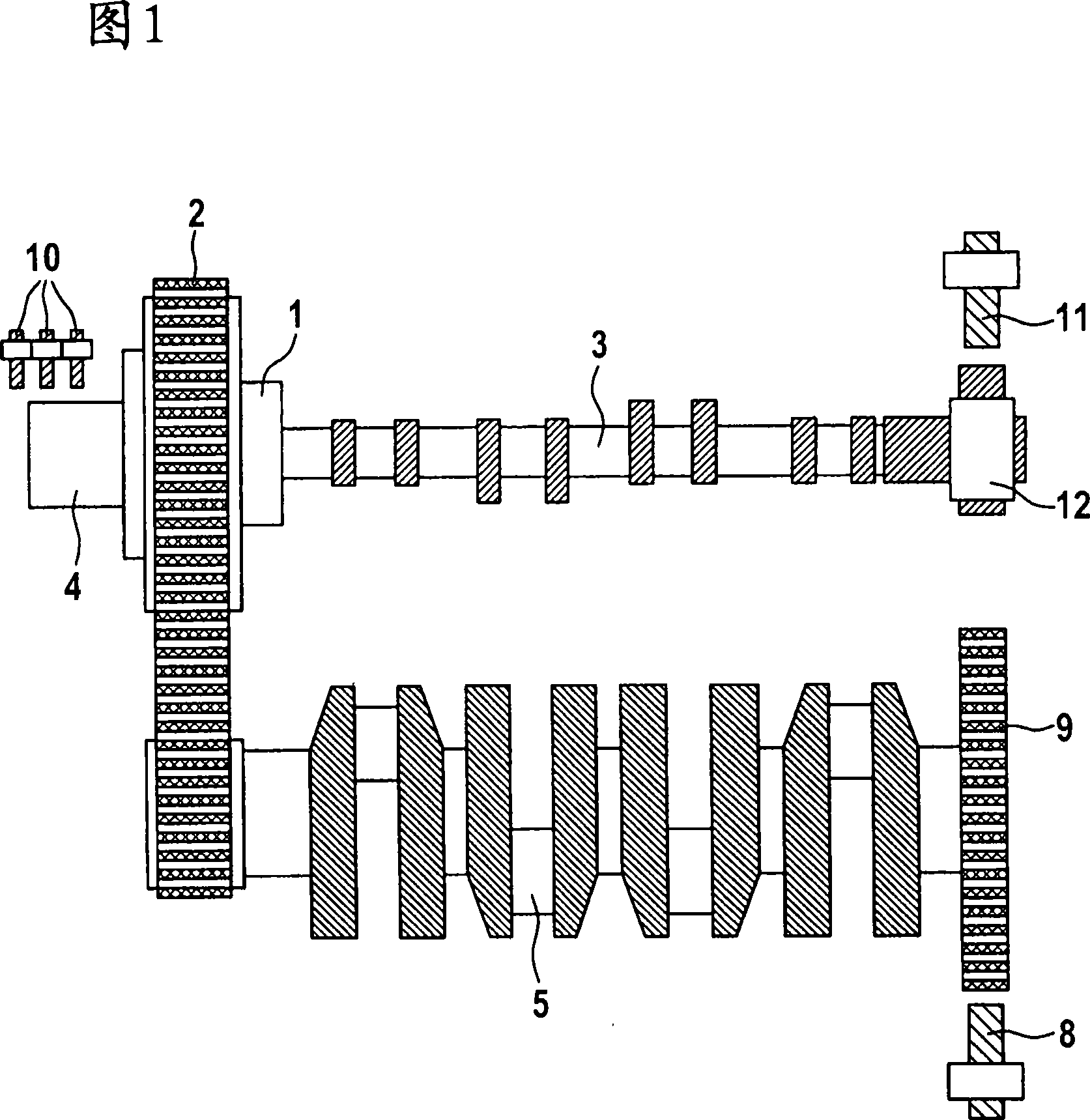
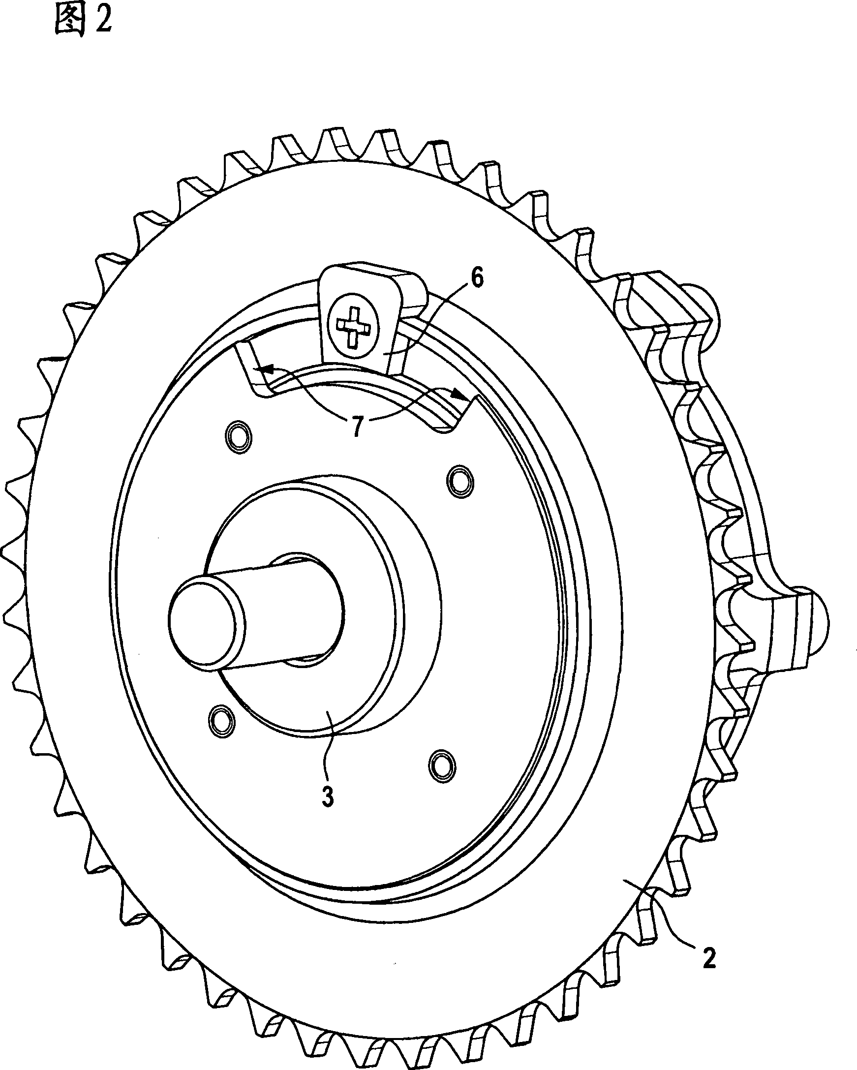
[0020] A device for adjusting the angular position of the camshaft 3 relative to the crankshaft 5 of a reciprocating piston internal combustion engine has an adjusting transmission 1 according to FIG. A three-shaft transmission with a driven shaft and an adjusting shaft. The adjusting gear can be a planetary gear, preferably a planetary gearbox.

[0021] The drive shaft is connected in a rotationally fixed manner to a camshaft gear 2 which is drive-connected in a known manner via a chain or a toothed belt to a crankshaft gear arranged in a rotationally fixed manner on the crankshaft 5 of the internal combustion engine. The driven shaft is connected in a rotationally fixed manner to the camshaft 3 . The adjustment shaft is connected in a rotationally fixed manner to the rotor of an electric motor 4 . The adjusting gear 1 is integrated in the hub of the camshaft gear 2 .

[0022] In order to limit the angle of rotation between the camshaft 3 and the crankshaft 5 of the intern...


PUM


Abstract

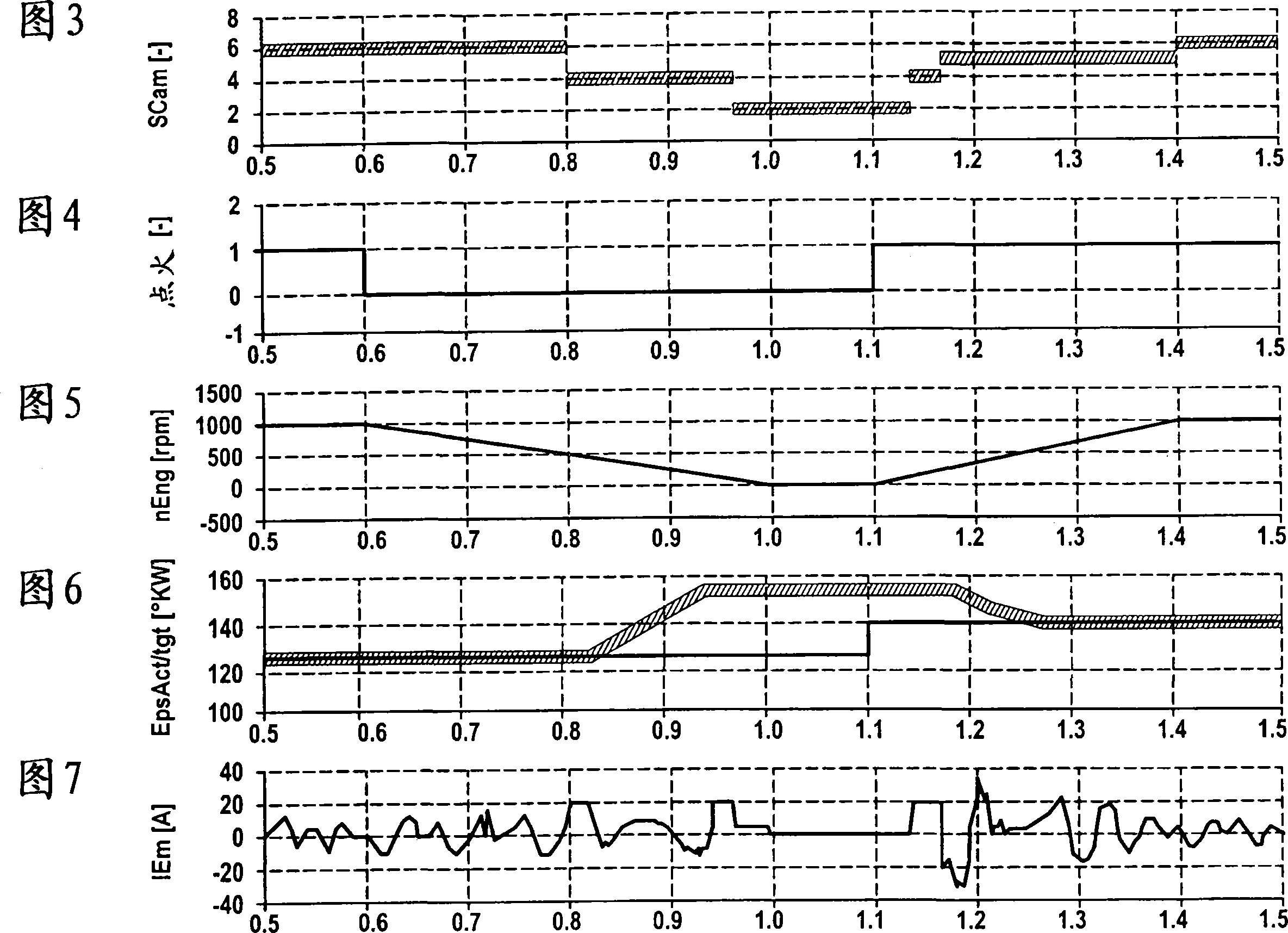
In a method for adjusting the rotational angular position of a camshaft relative to a crankshaft of a reciprocating internal combustion engine, the crankshaft is connected to the camshaft via a three-shaft transmission. The three-shaft transmission has a drive shaft fixed to the crankshaft, a driven shaft fixed to the camshaft and an adjusting shaft driven by an electric motor. A crankshaft sensor signal is detected, which changes its state when a rotational angle of the crankshaft changes. In addition, an adjusting shaft sensor signal is detected, which changes its state when an indexing change of the adjusting shaft occurs. Starting from a reference angle of rotation value, a phase angle signal is tracked and adjusted to a provided target phase angle signal when a state change of the crankshaft sensor signal and / or the adjustment shaft sensor signal is made. The ignition of the internal combustion engine is then switched off and / or the rotational speed of the crankshaft is reduced below a predetermined minimum rotational speed value. While the crankshaft and / or the camshaft are still rotating, the electric motor is supplied with current in such a way that the camshaft rotates in the direction of a predetermined reference position relative to the crankshaft. When the internal combustion engine is next started, the camshaft and the crankshaft are positioned in reference positions and detected by means of a sensor. The phase angle signal is set to a reference value and then adjusted to the desired phase angle signal.

Description

technical field [0001] The invention relates to a method for adjusting the angular position of the camshaft of a reciprocating piston internal combustion engine relative to the crankshaft, wherein the crankshaft is in driving connection with the camshaft via an adjusting gear, the adjusting gear being constituted by a Three-shaft transmission of a driving shaft, a driven shaft fixed on a camshaft, and an adjusting shaft in driving connection with an electric motor, in which the crankshaft rotates and detects a crankshaft sensor signal which changes its state when a rotational angle of the crankshaft changes , wherein the adjustment shaft rotates and detects an adjustment shaft sensor signal, which changes its state upon an index change of the adjustment shaft, wherein starting from a reference angle value assigned to a reference angle position, the crankshaft sensor signal and / or adjustment Tracking a phase angle signal during a state change of the shaft sensor signal, wherein...

Claims


Application Information

Patent Timeline
IPC IPC(8): F01L1/344F01L1/352
CPCF01L2103/02F01L2800/14F01L2820/01F01L1/352F01L1/344F01L2303/02
Inventor M·源H·德尔H·施托尔克
Owner SCHAEFFLER TECH AG & CO KG
Why Eureka
Eureka Blog
Learn More