Electronic gas meter for mass and flow

A mass flow and gas metering technology, which is applied to indirect mass flowmeters, mass flow measurement devices, volume metering, etc., can solve problems such as lack of prevention, difference in measurement accuracy, and damage to measurement components, and achieve simple structure, improved safety, and Facilitate manufacturing and assembly effects

Inactive Publication Date: 2008-02-20
CHONGQING QIANWEI SCI & TECH GRP +1
View PDF0 Cites 33 Cited by
  • Summary
  • Abstract
  • Description
  • Claims
  • Application Information

AI Technical Summary

Problems solved by technology

However, the measurement circuit of the ultrasonic flowmeter of this meter is more complicated than that of ordinary flowmeters, because the flow velocity of gas in general industrial measurement is often several meters per second, and the maximum change of the measured gas flow velocity and flow rate to the sound velocity is also 10 -3 Magnitude
If the accuracy of measuring the flow velocity is required to be 1%, the accuracy of the measurement of the velocity of sound needs to be 10 -5 ~10 -6 Order of magnitude, so it must have a perfect measurement line to achieve, the design is more difficult
And this kind of electronic gas meter with ultrasonic measurement measures gas volume flow instead of mass flow, and the measurement accuracy will also vary due to changes in ambient temperature and pipeline pressure fluctuations
[0004] At the same time, because the existing membrane gas meters and electronic gas meters do not have a dust-proof structure to prevent dust impurities such as iron tetroxide and sulfide from adhering to the measuring parts in the gas, it is easy to be damaged by dust impurities. Adhesion will affect the measurement accuracy of the gas meter, and even cause damage to the measurement parts in severe cases, reducing the service life of the gas meter

Method used


Image

  • Electronic gas meter for mass and flow
  • Electronic gas meter for mass and flow

Examples


Embodiment Construction

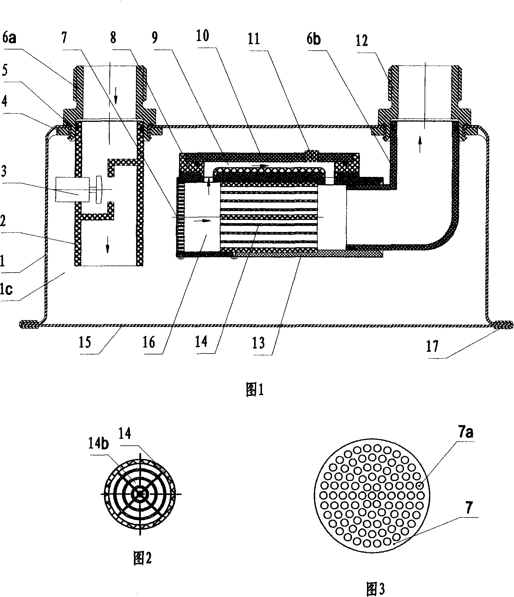
[0016]Referring to Figures 1 to 4, the housing 1 of the electronic mass flow gas meter is a housing with an airtight cavity 1c, and the inlet port and the outlet port of the housing 1 are fixedly connected with pipe joints 6a and 6b respectively. , the pipe joints 6a and 6b of the air inlet and air outlet interfaces are respectively riveted and fixed on the housing 1 through the gaskets 4 matched therewith, and a sealing ring 5 is provided between the pipe joints and the housing to seal the riveting place. When riveting, the riveted end of the pipe joint 6a, 6b passes through the hole on the shell 1 and puts the gasket 4, and the contact between the pipe joint and the shell is covered with a rubber sealing ring 5, and the pipe joint, the gasket, the sealing ring and the shell Tightly connected and fixed together to form a sealed connection. The bottom of the shell is covered by the bottom plate 15. The bottom plate 15 and the flanging of the shell 1 are pressed together by the ...


PUM


Abstract

The utility model discloses an electronic mass flow gas meter; an airtight cavity is arranged in the casing of the gas meter. The gas pipelines in the casing are divided into an independent gas inlet pipe, and a flow testing tube and gas outlet pipe, which are connected together. The gas inlet and outlet pipes are respectively connected with the gas outlet and inlet interfaces of the casing. The lower end of the flow testing tube is connected with the gas outlet pipe and horizontally suspended inside the casing. A main flow airway and a bypass airway are arranged in the flow testing tube; wherein, a by-passing device is arranged in the main flow airway and arranged between the two through holes for communicating the bypass airways. The cross-sectional area of the bypass airway is smaller than that of the main flow airway, and a signal sensing module of thermal mass flow sensors is arranged on the inner wall of the bypass airway for detection. The utility model can carry out mass flow measurement of the passing gas, and can prevent the dust in the gas from attaching to the sensing element, thus improving the measuring accuracy and service life of the gas meters.

Description

technical field [0001] The invention relates to a gas meter, in particular to an electronic mass flow gas meter. Background technique [0002] The current household gas meter is usually a membrane gas meter with mechanical transmission metering, which is based on the measurement of the volume flow of gas. The specific work is that when the gas enters the airbag, the airbag is inflated by the gas pressure, pushing the diaphragm to move, driving the connecting rod mechanism to move, pushing the valve cover to rotate repeatedly, so that the valve cover is opened or closed, and the airbag deflates after the gas flows out. In this way, the total gas flow rate is determined by calculating the product of the switching times of the airbag and the volume of the airbag. The mechanical structure of the diaphragm gas meter is very complex, and there are many parts, making it difficult to process and assemble. Especially during factory calibration, the conversion gear needs to be repla...

Claims


Application Information

Patent Timeline
Patent Type & Authority Applications(China)
IPC IPC(8): G01F1/76G01F1/86G01F15/00G01F15/12
Inventor 王宏臣刘晓阳张陆军李原庄利锋蔡柏春许建伟李斌
Owner CHONGQING QIANWEI SCI & TECH GRP
Why Eureka
Try Eureka