High precision broad frequency contaminated insulator leakage current sensor

A leakage current and wide-band technology, which is applied in the field of insulator AC leakage current detection sensors, can solve the problems of incompatibility between frequency band and sensitivity, large impact of on-site interference, and poor application effect, so as to improve anti-interference ability, ensure response sensitivity, suppress Effects of Electromagnetic Interference

Inactive Publication Date: 2008-02-20
CHONGQING UNIV
View PDF1 Cites 27 Cited by
  • Summary
  • Abstract
  • Description
  • Claims
  • Application Information

AI Technical Summary

Problems solved by technology

However, both theory and practice have proved that the core-through current sensor has its own inherent defects: ① low precision under small current signals; ② inability to balance frequency band and sensitivity; ③ greatly affected by

Method used


Image

  • High precision broad frequency contaminated insulator leakage current sensor
  • High precision broad frequency contaminated insulator leakage current sensor
  • High precision broad frequency contaminated insulator leakage current sensor

Examples


Example Embodiment

[0033] Example 1

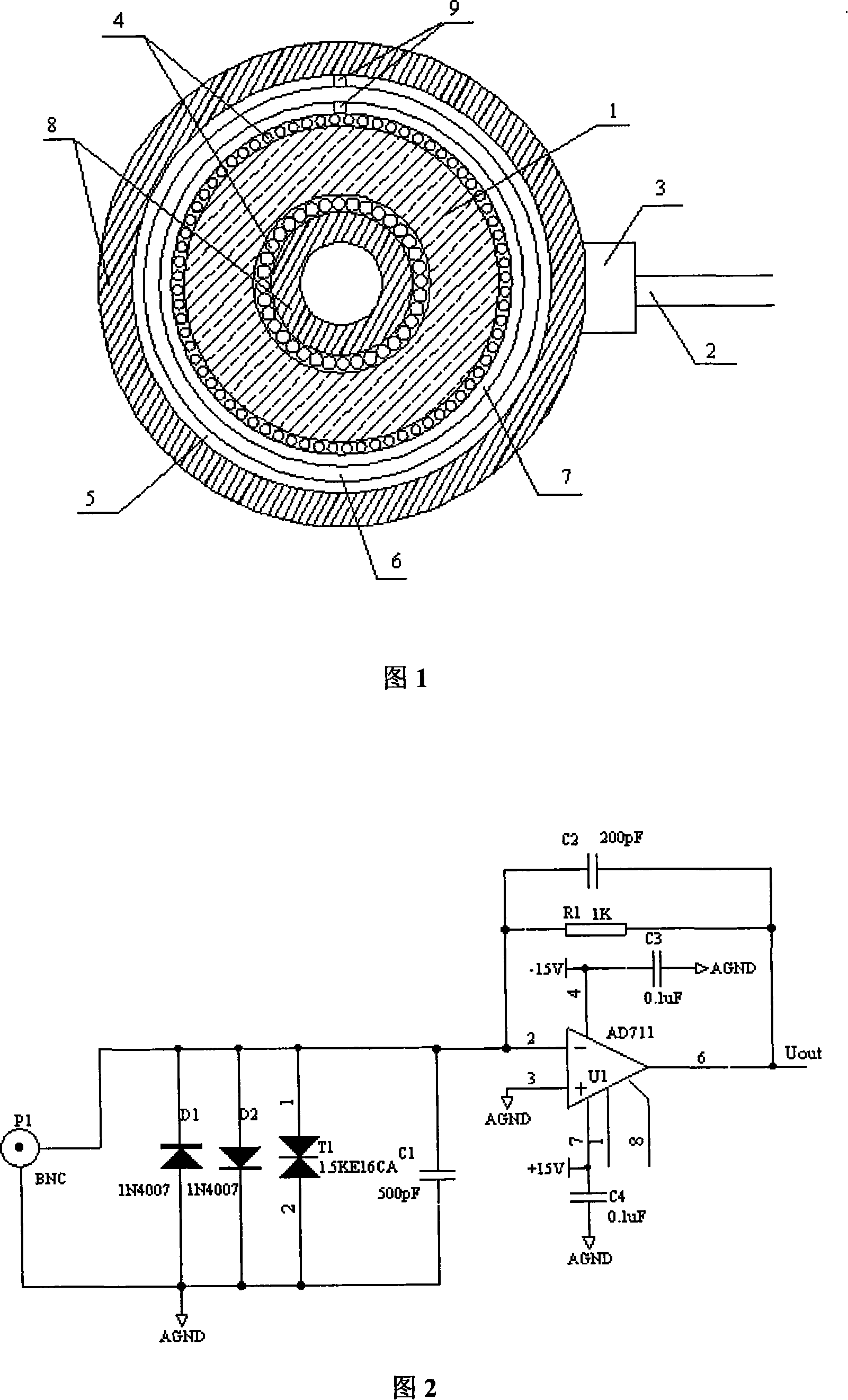
[0034] As shown in Figures 1 and 2, a high-precision broadband dirty insulator leakage current sensor mainly includes two parts, the Rogowski coil and the integral amplifier unit, which are connected by a coaxial cable 2 . The Rogowski coil is composed of a nanocrystalline alloy annular iron core 1 , a winding 4 , a double-layer shielding structure, an engineering plastic shell 8 and a coaxial cable connector 3 . Inside the housing 8, a winding 4 with 120 turns of enameled wire with a diameter of 0.19 mm, a nanocrystalline alloy annular iron core 1 and a double-layer shielding structure are respectively arranged from the inside to the outside, and the winding 4 is wound on the nanocrystalline alloy annular On the iron core 1, a double-layer shielding structure is arranged on the upper, lower and outer sides of the coil. The inner layer is a copper shielding layer 7, and the outer layer is an iron shielding layer 5, both of which have a thickness of 0.5 mm to...

Example Embodiment

[0036] Example 2

[0037] A high-precision broadband dirty insulator leakage current sensor mainly includes two parts, a Rogowski coil and an integral amplifier unit, which are connected by a coaxial cable 2 . The Rogowski coil is composed of a nanocrystalline alloy annular iron core 1 , a winding 4 , a double-layer shielding structure, an engineering plastic shell 8 and a coaxial cable connector 3 . Inside the housing 8, a winding 4 with 120 turns of enameled wire with a diameter of 0.19 mm, a nanocrystalline alloy annular iron core 1 and a double-layer shielding structure are respectively arranged from the inside to the outside, and the winding 4 is wound on the nanocrystalline alloy annular On the iron core 1, a double-layer shielding structure is arranged on the upper, lower and outer sides of the coil. The inner layer is a copper shielding layer 7, and the outer layer is an iron shielding layer 5, both of which have a thickness of 0.3 mm to shield external electromagnetic...


PUM

PropertyMeasurementUnit
Thicknessaaaaaaaaaa
Thicknessaaaaaaaaaa
Sensitivityaaaaaaaaaa

Abstract

The utility model discloses a leakage current sensor with high precision broadband pollution insulator, relating to an insulator AC leakage current detection sensor. The sensor of the utility model mainly comprises Rogowski coil and an integral amplifying unit and a coaxial cable; the Rogowski coil and the integral amplifying unit are connected through the coaxial cable. The utility model has the advantages of strongly anti-interfering ability, high detecting precision, sensibility up to 8.3mV/mA, bandwidth up to 2Hz to 100kHz, amplitude range of detecting current reaching 10MuA to 450mA; thus the utility model is widely used in online monitoring of insulator leakage current of power transmission line and transformer station and is also used for micro-current or small current monitoring of other electrical and electronic devices such as grounding current, leakage current and harmonic current.

Description

technical field [0001] The invention belongs to the technical field of electrical equipment insulation monitoring, in particular to an insulator AC leakage current detection sensor. Background technique [0002] Insulator pollution is a large-scale regional problem. Once a pollution flashover accident occurs, it will affect a large area and last for a long time. It is one of the most serious problems that threaten the safe transmission of power systems and must be taken seriously. With the development of industrial economy and the continuous improvement of transmission voltage level, the pollution flashover prevention of insulators has become one of the urgent research issues in today's power system. [0003] After the insulator surface is polluted, pollution flashover may occur when encountering meteorological conditions such as fog, dew, drizzle, and snowfall. Under humid conditions, the greater the amount of pollution on the insulator, the greater the content of water-so...

Claims


Application Information

Patent Timeline
IPC IPC(8): G01R31/00G01R31/02G01R31/12G01R19/165
Inventor 杜林李先志姚陈果胡建林李剑蒋兴良孙才新
Owner CHONGQING UNIV
Why Eureka
Try Eureka