Optical movement sensing device and its sensing method

A motion device and optical motion technology, applied in the field of optical sensing, can solve the problems of affecting the light reflection effect, affecting the efficiency, and unable to guarantee reflected light, etc., to achieve the effect of increasing the aesthetics, the weight and the user experience.

Inactive Publication Date: 2008-02-20
APEXONE MICROELECTRONICS
View PDF0 Cites 8 Cited by
  • Summary
  • Abstract
  • Description
  • Claims
  • Application Information

AI Technical Summary

Problems solved by technology

However, referring to FIG. 2, on the other hand, setting the angle between the incident light 96 and the reflected light 95 as an obtuse angle can effectively reduce the thickness of the mobile phone, but this will affect the light reflection effect, that is, Said, there is no guarantee that enough reflected light hits the photosensitive device 92
It should be pointed out that the optical motion sensing device realizes the sensing function by means of the reflected light generated by the reflection of the incident light by the optical trackball. efficiency

Method used


Image

  • Optical movement sensing device and its sensing method
  • Optical movement sensing device and its sensing method
  • Optical movement sensing device and its sensing method

Examples


Embodiment Construction

[0038] The specific embodiments of the present invention will be described in further detail below with reference to the accompanying drawings.

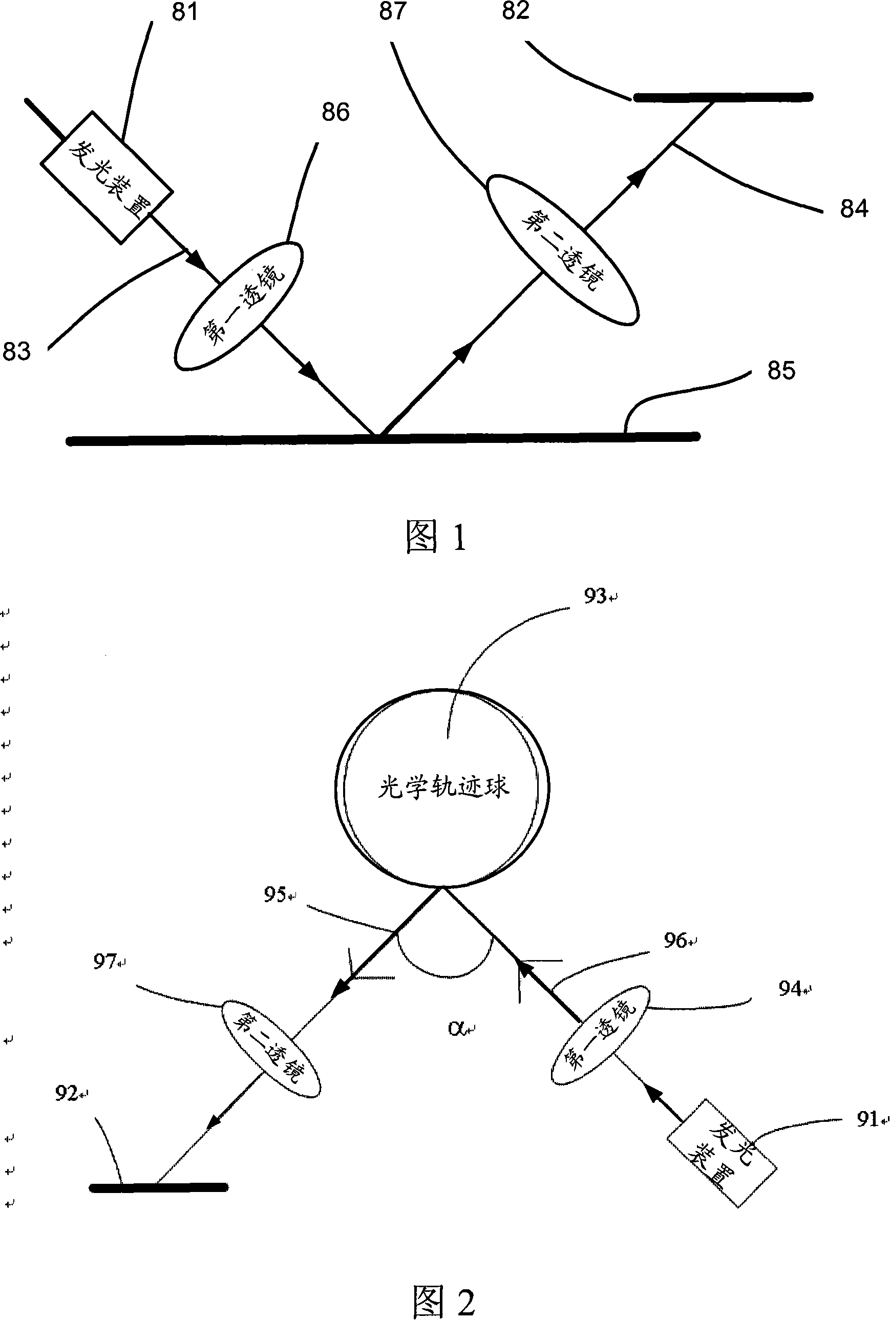
[0039] Those skilled in the art should understand that the size of each element or device in the drawings may be exaggerated to facilitate clearer description. In addition, it should also be understood that when it is mentioned that light emitted from one optical element is directed to another optical element, one or more intermediate optical elements can be arranged between the two, or no element can be placed on the optical path. Shoot directly to the surface of another optical element. The same reference numerals indicate the same elements throughout the text. In the following description, the “first” and “second” mentioned are only used to distinguish different elements and / or features of different elements, unless otherwise specified.

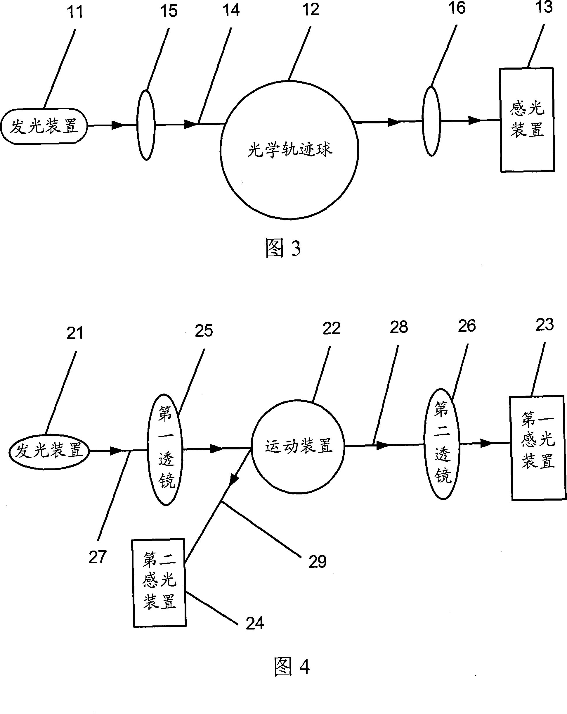
[0040] Fig. 3 shows a schematic structural diagram of a first embodiment of an optical motion sen...


PUM


Abstract

The utility model discloses an optical motion perception device and an optical motion perception process. The device comprises a light producing device emitting light, an optics contrail ball or a motion unit, and a sensitization unit for light perception and image processing. The process comprises the light producing device emitting the light and the optics contrail ball or the motion unit which receives the emission light. As the optics contrail ball or the motion unit rolls, the texture information is loaded to the transmitting lights which are received and processed by the light perception unit to output the signal. The output signal is converted into the identification control signal controlling the movement of the pointer. By the appliance of the device and the process, movable equipments or portable electronic equipments can more compact size and lighter weight. Additionally, the transmission way of the initiative luminescence can increase the perception efficiency of the perception unit on the light.

Description

Technical field [0001] The present invention relates to optical sensing technology, in particular to optical motion sensing and processing technology. Background technique [0002] Generally, a general optical motion sensing device includes a light emitting device, a working surface for light reflection, and a photosensitive device. Figure 1 shows a schematic structural diagram of an optical motion sensing device in the prior art. As shown in Figure 1, the optical motion sensing device has: a light-emitting device 81, which contains a light source for emitting light to the working surface; and a light-sensing device 82 , Used to detect feature changes of the work surface 85 (such as a mouse pad or a desktop). Wherein, the optical motion sensing device may also include a first lens 86 and a second lens 87, and the symbol "83" represents the incident light emitted by the light emitting device 81, and the symbol "84" represents the light emitted to the photosensitive device through ...

Claims


Application Information

Patent Timeline
Patent Type & Authority Applications(China)
IPC IPC(8): G06F3/033G02B17/08G06F3/0354
Inventor 高勇刘建
Owner APEXONE MICROELECTRONICS
Why Eureka
Try Eureka