Method for producing dental orthodontic supporter groove

A technology for orthodontic brackets and production methods, applied in the direction of brackets, can solve problems such as rough surfaces, low production efficiency, and high cost, and achieve the effects of high product precision, high production efficiency, and easy processing

Inactive Publication Date: 2008-02-27
长沙市天天齿科器材有限公司
View PDF0 Cites 2 Cited by
  • Summary
  • Abstract
  • Description
  • Claims
  • Application Information

AI Technical Summary

Problems solved by technology

Due to the influence of shrinkage instability and other factors in the casting process, the bracket body processed by casting method also has the problems of rough surface and difficult to guarantee the accuracy of external dimensions
Therefore, the surface roughness and precision of the brackets processed by these methods cannot meet the clinical requirements, and the processing procedures are complicated, the cost is high, and the production efficiency is low.

Method used


Image

  • Method for producing dental orthodontic supporter groove

Examples


Embodiment Construction

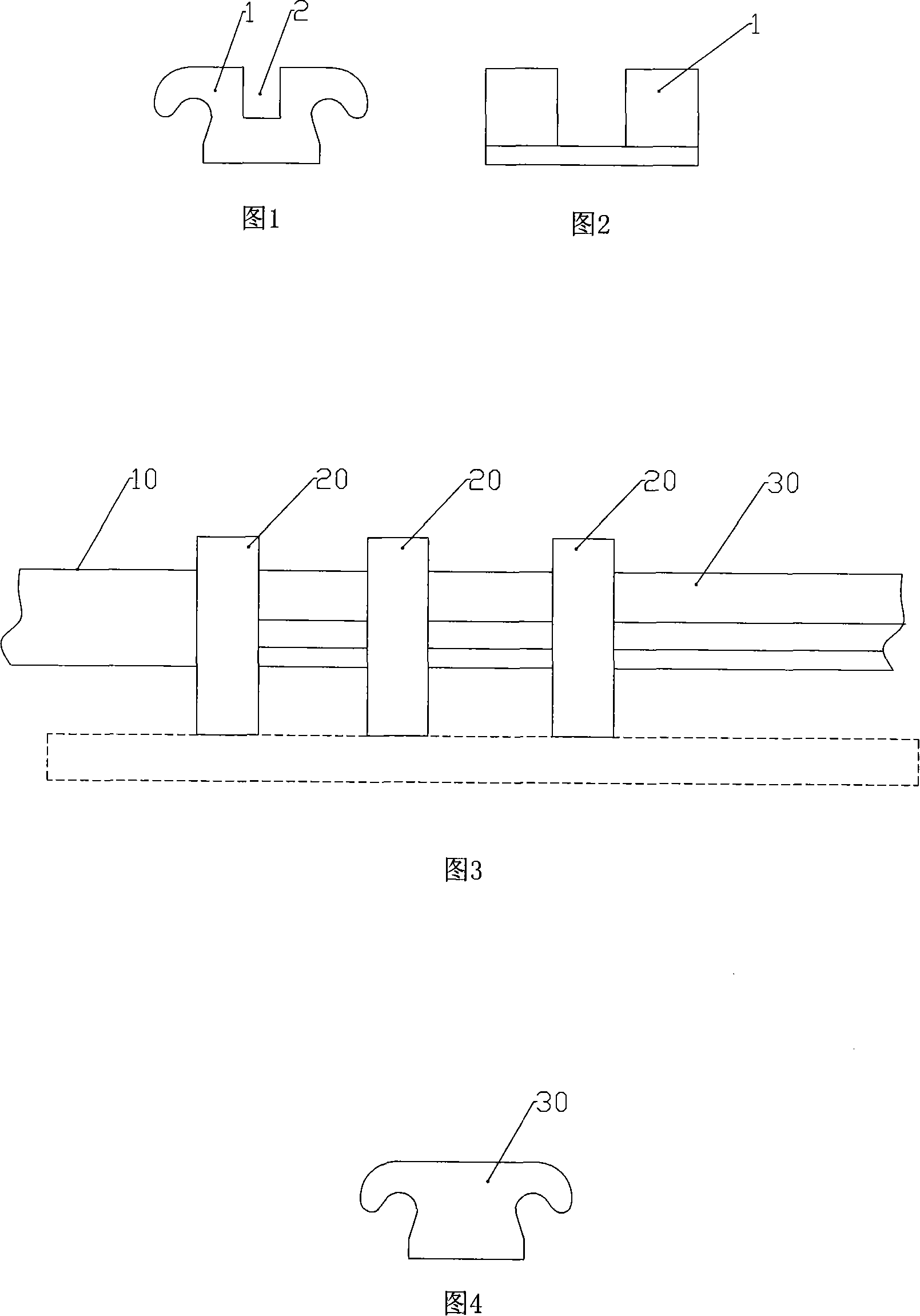
[0012] The present invention will be further described below in conjunction with the accompanying drawings and specific embodiments, so as to help understand the content of the present invention.

[0013] As shown in Figure 3, a kind of production method of dental orthodontic bracket body, the orthodontic bracket body fine billet 30 that strip-shaped blank 10 is cold-drawn and extruded into strip shape by calendering die 20, orthodontic bracket body fine The cross-sectional shape of the blank 30 is shown in FIG. 3 , and its surface roughness and external dimension accuracy can meet the clinical requirements of orthodontic brackets without barrel grinding and polishing.

[0014] The strip blank 30 is machined to form archwire grooves, and then cut into independent orthodontic bracket bodies. Obtain the dental orthodontic bracket body shown in Figure 1 and Figure 2 that meets the requirements.

[0015] According to needs, the number of calendering dies 20 can be multiple, for e...


PUM


Abstract

The invention discloses a making method of dental pincushion distortion tray groove, which comprises the following steps: rolling die; doing cold drawing; squeezing to form bar-shaped fine blank of pincushion distortion groove; manufacturing the fine blank into arch wire trench; cutting into individual product.

Description

technical field [0001] The invention relates to a production method of a dental orthodontic bracket body for dental orthodontics. Background technique [0002] Dental orthodontic brackets are equipment for orthodontics, and are key components of fixed orthodontic appliances. Its structure is shown in Figure 1 and Figure 2. For the correction of tooth deformity, usually several brackets are bonded to a row of teeth, and the arch wire is embedded in the arch wire groove 2 of each bracket body 1. In the process, the ligature wing of the bracket body is used to fix the dental arch wire on the bracket with the ligature wire, and the dental arch wire exerts various types of correction force on the teeth through the bracket, and gradually corrects the deformed teeth, thereby To achieve the purpose of orthodontics. [0003] For dental orthodontic brackets, the main problems to be solved are surface roughness (required Ra≤1.6μm) and precision. Only when the surface is smooth, can ...

Claims


Application Information

Patent Timeline
Patent Type & Authority Applications(China)
IPC IPC(8): A61C7/14
Inventor 唐正清吴自新
Owner 长沙市天天齿科器材有限公司
Why Eureka
Try Eureka