Supercharge Your Innovation With Domain-Expert AI Agents!

Liquid crystal display device and its driving method

A technology of liquid crystal display and driving method, which is applied in the field of liquid crystal display and its driving, and can solve the problems that the response time cannot keep up, brightness loss, etc.

Active Publication Date: 2010-06-09
AU OPTRONICS CORP
View PDF2 Cites 0 Cited by
  • Summary
  • Abstract
  • Description
  • Claims
  • Application Information

AI Technical Summary

Problems solved by technology

However, under the drive of high frequency 300Hz, if the response time of liquid crystal molecules cannot keep up, it may cause the loss of brightness

Method used


Image

  • Liquid crystal display device and its driving method
  • Liquid crystal display device and its driving method
  • Liquid crystal display device and its driving method

Examples


Embodiment Construction

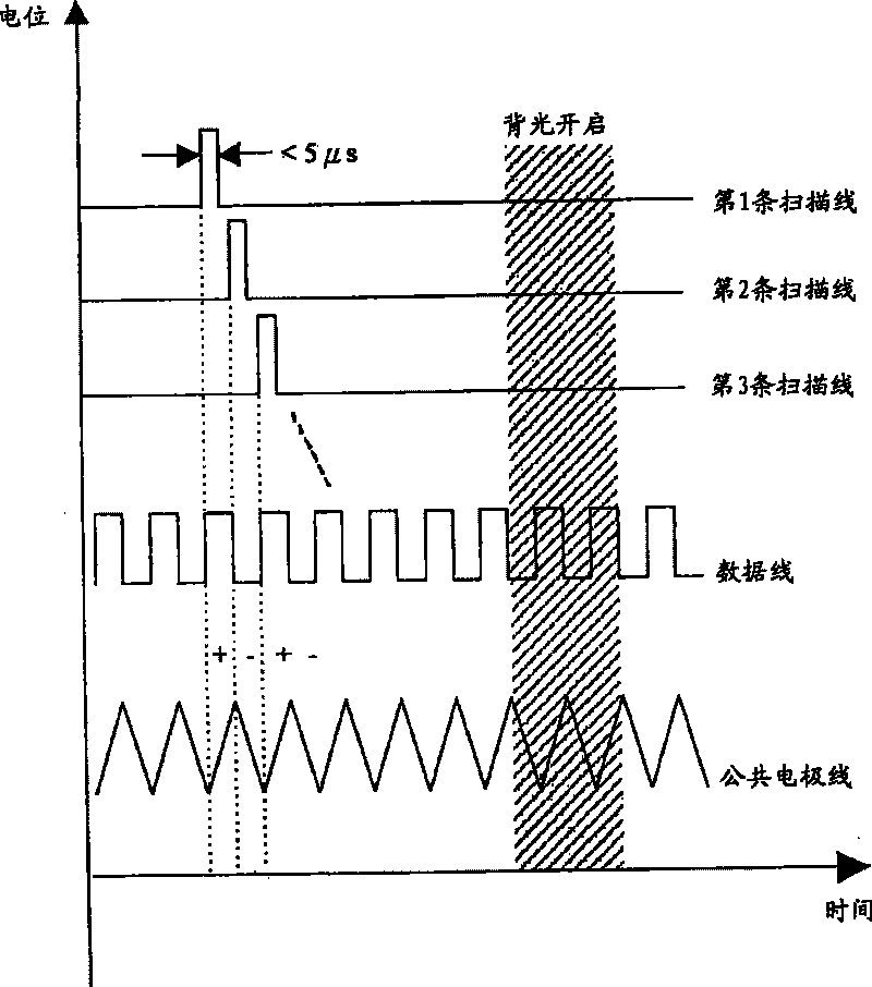
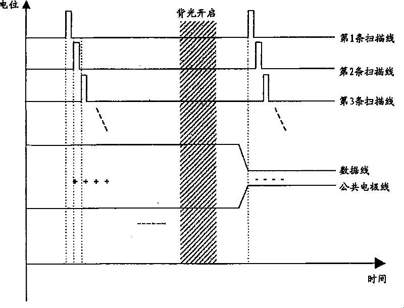
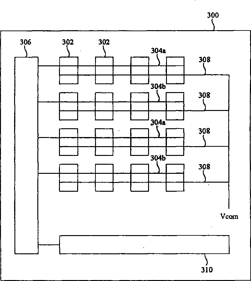
[0025] image 3 is a schematic diagram illustrating a liquid crystal display according to an embodiment of the present invention. The liquid crystal display 300 includes a plurality of pixel units 302 , a plurality of scan lines 304 a and 304 b , at least one scan driver 306 , and a plurality of common electrode lines 308 . Each scan line 304 a or 304 b is electrically connected to one end of a row of pixel units 302 . The pixel voltages of the pixel units 302 connected to the scan lines 304a of the first group and the pixel units 302 connected to the scan lines 304b of the second group have different polarities.

[0026] The scan driver 306 respectively sends a plurality of first turn-on pulses to the scan lines 304a of the first group in the first period of the predetermined time, and sends a plurality of second turn-on pulses to the second group in the second period of the predetermined time. The scan line 304b. Each common electrode line 308 is electrically connected to...


PUM


Abstract

A kind of liquid display drive method includes the scanning beam which can send several first unlock pulse to the first group in the first period of time of the preset time. The scanning beam which can send several second unlock pulse to the second group in the second period of time of the preset time. The image element pressure of the image element cell which links with the first group scanning beam and the second one has different polarity. Sends the commonality electric pole line signal toe the commonality electric pole in the preset time, the commonality electric pole line signal has different electrical level in the first period of time and the second one. It also discloses a kind of liquid display which uses the said drive method.

Description

technical field [0001] The present invention relates to a display and its driving method, in particular to a liquid crystal display and its driving method. Background technique [0002] figure 1 It is a signal timing diagram of a known line inversion driving method of a liquid crystal display, which shows the potential changes of the scanning lines, data lines and common electrode lines over time when the liquid crystal display is driven by the color sequential method (Color Sequential) . Under the architecture driven by the color sequence method, three sub-frames of primary colors such as RGB are needed to form a complete frame, so the driving frequency of one sub-frame is 180Hz. However, only a small part of the time (<5 μs) of a subframe is used for scanning lines, and most of the time is spent waiting for liquid crystal molecules to react and turn on the backlight. In addition, in order to reduce the phenomenon that the brightness of the panel decreases sequentiall...

Claims


Application Information

Patent Timeline
Patent Type & Authority Patents(China)
IPC IPC(8): G09G3/36G09G3/20G09G5/02G09G3/34G02F1/133
Inventor 黄雪瑛江明峰
Owner AU OPTRONICS CORP
Features
  • R&D
  • Intellectual Property
  • Life Sciences
  • Materials
  • Tech Scout
  • Unparalleled Data Quality
  • Higher Quality Content
  • 60% Fewer Hallucinations
Learn More