
Injection pump for internal-combustion engine and internal-combustion engine

A technology for injection pumps and internal combustion engines, applied in fuel injection pumps, fuel injection devices, machines/engines, etc., can solve problems such as suction hole cavitation, achieve long service life, reduce wear, and increase maintenance intervals

Active Publication Date: 2012-11-07
MAN ENERGY SOLUTIONS SA
View PDF0 Cites 0 Cited by
  • Summary
  • Abstract
  • Description
  • Claims
  • Application Information

AI Technical Summary

Problems solved by technology

[0003] The pressure prevailing at the suction hole is therefore subject to strong and shock-like changes, whereby cavitation can occur at the suction hole

Method used


Image

  • Injection pump for internal-combustion engine and internal-combustion engine
  • Injection pump for internal-combustion engine and internal-combustion engine
  • Injection pump for internal-combustion engine and internal-combustion engine

Examples


Embodiment Construction

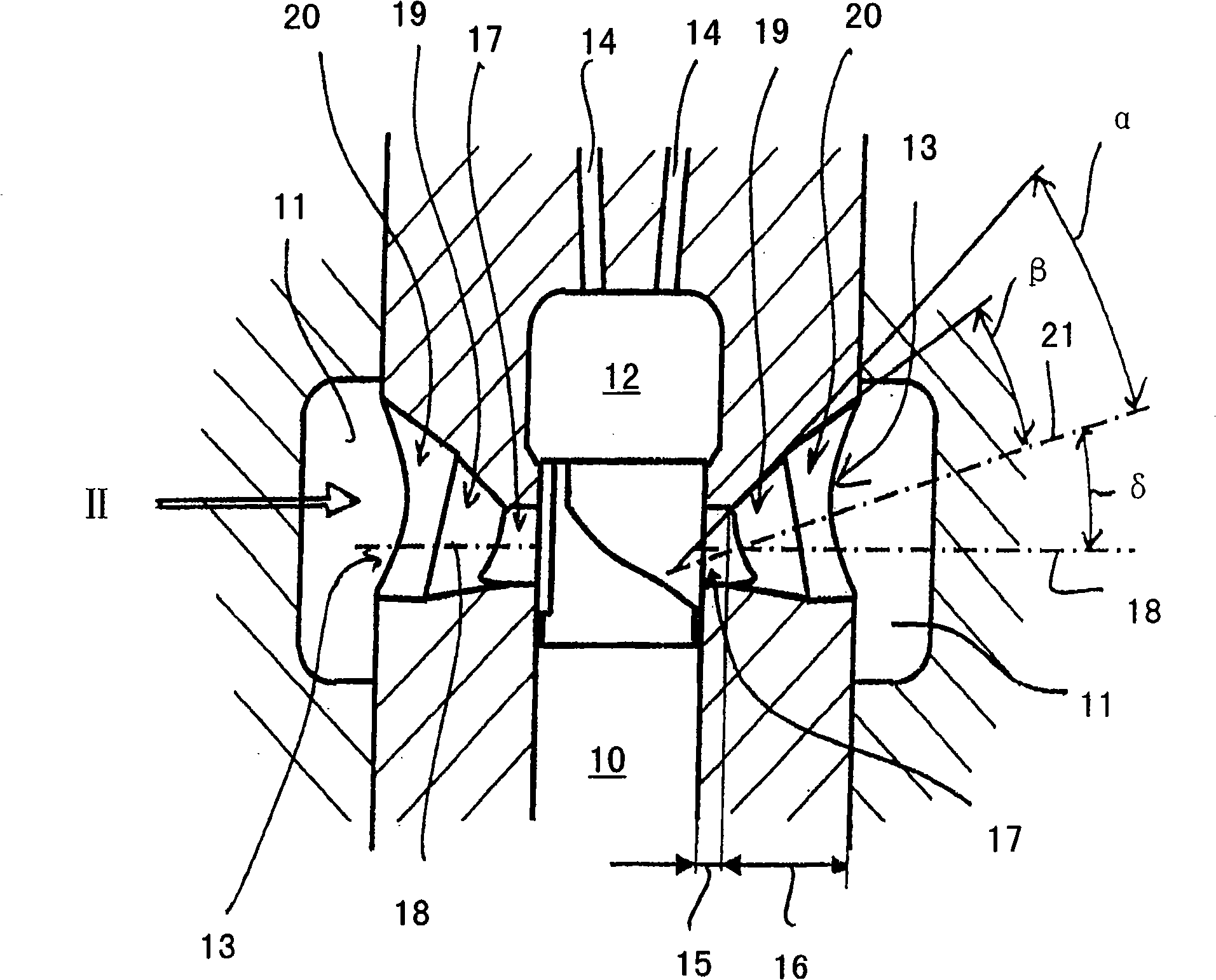
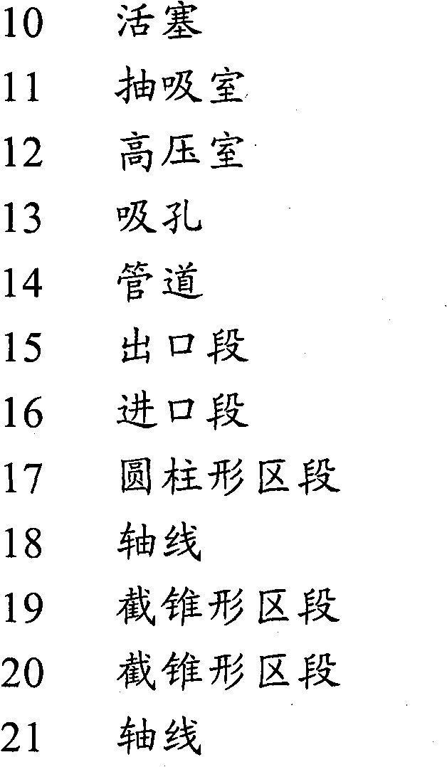
[0011] figure 1 A so-called inclined-edge controlled piston high-pressure injection pump for a diesel internal combustion engine is shown in a schematic partial cross-section, wherein the injection pump comprises a piston 10 which cooperates with a suction chamber 11 and a high-pressure chamber 12 of the injection pump . The suction chamber 11 is usually connected to the high-pressure chamber 12 via two suction holes 13 . It is pointed out that only one suction hole or more than two suction holes may also be present. Depending on the position of the piston 10 , the piston either releases the suction opening 13 or 10 and closes the suction opening 13 . With the piston 10 closing the suction opening 13 (during most of the upward movement of the piston 10 ) the flow of fuel from the suction chamber 11 of the injection pump into the high pressure chamber 12 is inhibited.

[0012] On the other hand, when the piston 10 releases the suction opening 13 and there is a lower pressure...


PUM


Abstract

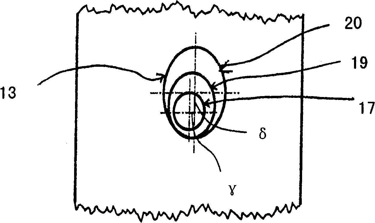
The present invention relates to an injection pump for internal combustion engine which has at least one piston (10), wherein, a pump chamber (11) and a high pressure chamber (12) connected via two suction holes (13) work together with the piston or each piston (10) in order to make the piston or each piston (10) close the suction hole or each suction hole (13) at a first position and to restrain the fuel flow from the pump chamber (11) to the high pressure chamber (12), and the piston or each piston (10) will release the suction hole or each suction hole (13) at a second position in order to fill the high pressure chamber (12) with fuel from the pump chamber (11). The suction hole or each suction hole (13) has a cylinder type section (17) adjacent to the high pressure chamber (12), wherein, the cylinder type section (17) is connected with at least two truncated cone shape sections (19, 20), the axes (21) of which rotates or declines relative to the axes (18) of the cylinder type section (17) in horizontal direction or vertical direction.

Description

technical field [0001] The invention relates to injection pumps for internal combustion engines, ie fuel injection pumps. The invention also relates to an internal combustion engine. Background technique [0002] Piston high-pressure fuel injection pumps for internal combustion engines controlled by the hypotenuse known from practice usually have a piston, with an intake chamber and a high-pressure chamber interacting with the piston of the high-pressure injection pump. The suction chamber and the high-pressure chamber of the injection pump are usually connected to one another via two suction holes, wherein the piston of the high-pressure injection pump closes the suction hole in a first position and thereby suppresses a fuel flow from the suction chamber to the high-pressure chamber. In the second position of the piston, the piston releases the suction opening and can thus fill the high-pressure chamber with fuel from the suction chamber. The fuel reaches the suction cham...

Claims


Application Information

Patent Timeline
Patent Type & Authority Patents(China)
IPC IPC(8): F02M59/44
CPCF02M59/44F02M59/10F02M59/38
Inventor C·施罗特
Owner MAN ENERGY SOLUTIONS SA
Learn More