Measurement mechanism and measurement method for crankshaft assembly dynamic poise

A technology of measuring device and measuring method, which is applied in the direction of measuring device, static/dynamic balance test, machine/structural component test, etc., can solve the problems of not being able to meet the fast and precise inspection well, and spend a lot of labor, and save time. The effect of reducing labor and improving measurement accuracy

Inactive Publication Date: 2008-03-05
重庆迪佳科技股份有限公司
View PDF0 Cites 14 Cited by
  • Summary
  • Abstract
  • Description
  • Claims
  • Application Information

AI Technical Summary

Problems solved by technology

Since it is required to repeatedly start and stop the motor and continuously loosen, clamp and rotate the fixture on the balance frame during the test, the time period for testing a s

Method used


Image

  • Measurement mechanism and measurement method for crankshaft assembly dynamic poise
  • Measurement mechanism and measurement method for crankshaft assembly dynamic poise

Examples


Embodiment Construction

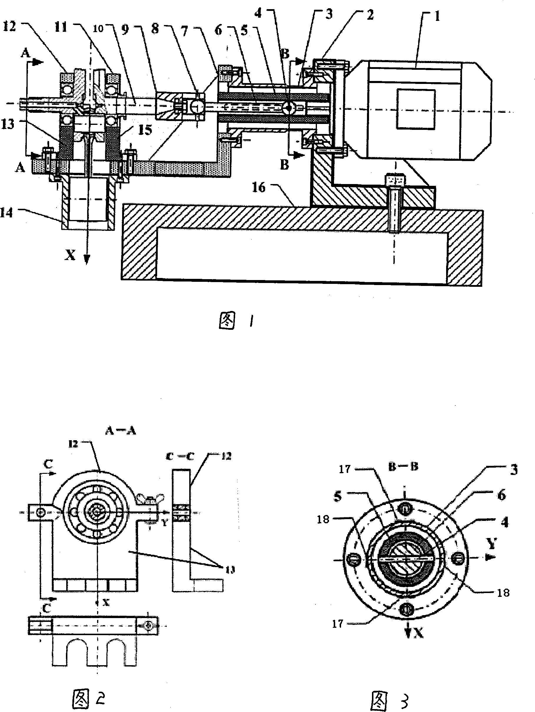
[0016] Referring to Fig. 1-Fig. 3, a measuring device for dynamic balance of a crankshaft assembly, the device includes a motor 1, a rectangular support seat 2, a cylindrical elastic support 3 with flanges at both ends, a hollow shaft sleeve 5, and a transmission shaft 6 , L-shaped bracket 7, connecting sleeve 9 and dynamic balancing machine bed 16, wherein: the right-angled support seat 2 is fixed on the dynamic balancing machine bed 16, and one end of the cylindrical elastic support 3 with flanges at both ends is fixed on the right-angled support On the vertical wall plate of the seat 2, there is a hole in the center of the wall plate, and the motor 1 is fixed on the other side opposite to the wall plate, and the L-shaped bracket 7 is fixed on the other end of the elastic support 3 of the hollow cylinder to form a cantilever; The shaft of 1 connects the hollow shaft sleeve 5 and the transmission shaft 6, and passes through the wall plate hole and the center of the inner hole ...


PUM


Abstract

The invention comprises a motor, a right angle support base, a cylinder elastic support whose both ends are flanges, a hollow shaft, a drive shaft, a L-shaped bracket, a dynamic balancing machine, and a train gauge coated on the cylinder elastic support. In the rotation plane of the crank shaft assembly, along with the orthogonal X,Y directions, simultaneously measuring the unbalance vibration or force signal of the crank shaft assembly running in high speed; after processed by computer, synthesizing the unbalance value along with different directions to form a closed curve graph. The invention also reveals a method thereof.

Description

technical field [0001] The invention relates to a device and method for measuring dynamic balance, in particular to a device for measuring dynamic balance of a crankshaft assembly and a method for measuring the same. Background technique [0002] Motorcycle engine crankshaft assembly includes left crankshaft, right crankshaft, crank pin, connecting rod, piston, piston pin, cylinder liner, left bearing, right bearing and other components. For the dynamic unbalanced force of the engine, it includes not only the unbalanced centrifugal force caused by the rotation of the left and right crankshafts, but also the unbalanced inertial force caused by the high-speed reciprocating motion of the connecting rod and piston along the central axis. Due to the joint action of the above two types of forces, the unbalanced inertial force of the crankshaft assembly on the rotary surface, that is, the X and Y planes, has i The features that vary by variation, i=1, 2,  …. Referring to Figure 6...

Claims


Application Information

Patent Timeline
IPC IPC(8): G01M1/22
Inventor 王成张济生
Owner 重庆迪佳科技股份有限公司
Why Eureka
Try Eureka