Chip packaging structure and method of producing the same

A technology of chip packaging structure and manufacturing method, which is applied in semiconductor/solid-state device manufacturing, electrical components, electric solid-state devices, etc., and can solve problems such as polluting circuits and polluting pads due to overflow of crystal glue

Inactive Publication Date: 2008-03-05
POWERTECH TECHNOLOGY
View PDF0 Cites 5 Cited by
  • Summary
  • Abstract
  • Description
  • Claims
  • Application Information

AI Technical Summary

Problems solved by technology

[0005] In order to solve the situation that the bonding pads on the chips are polluted by the overflow of the die-bonding glue when sticking the chips, one of the objects of the present invention is to provide a chip packaging structure and a manufacturing method thereof, which uses a stopper eleme

Method used


Image

  • Chip packaging structure and method of producing the same
  • Chip packaging structure and method of producing the same
  • Chip packaging structure and method of producing the same

Examples


Embodiment Construction

[0034] The detailed description is as follows, and the preferred embodiment is only for illustration and not intended to limit the present invention.

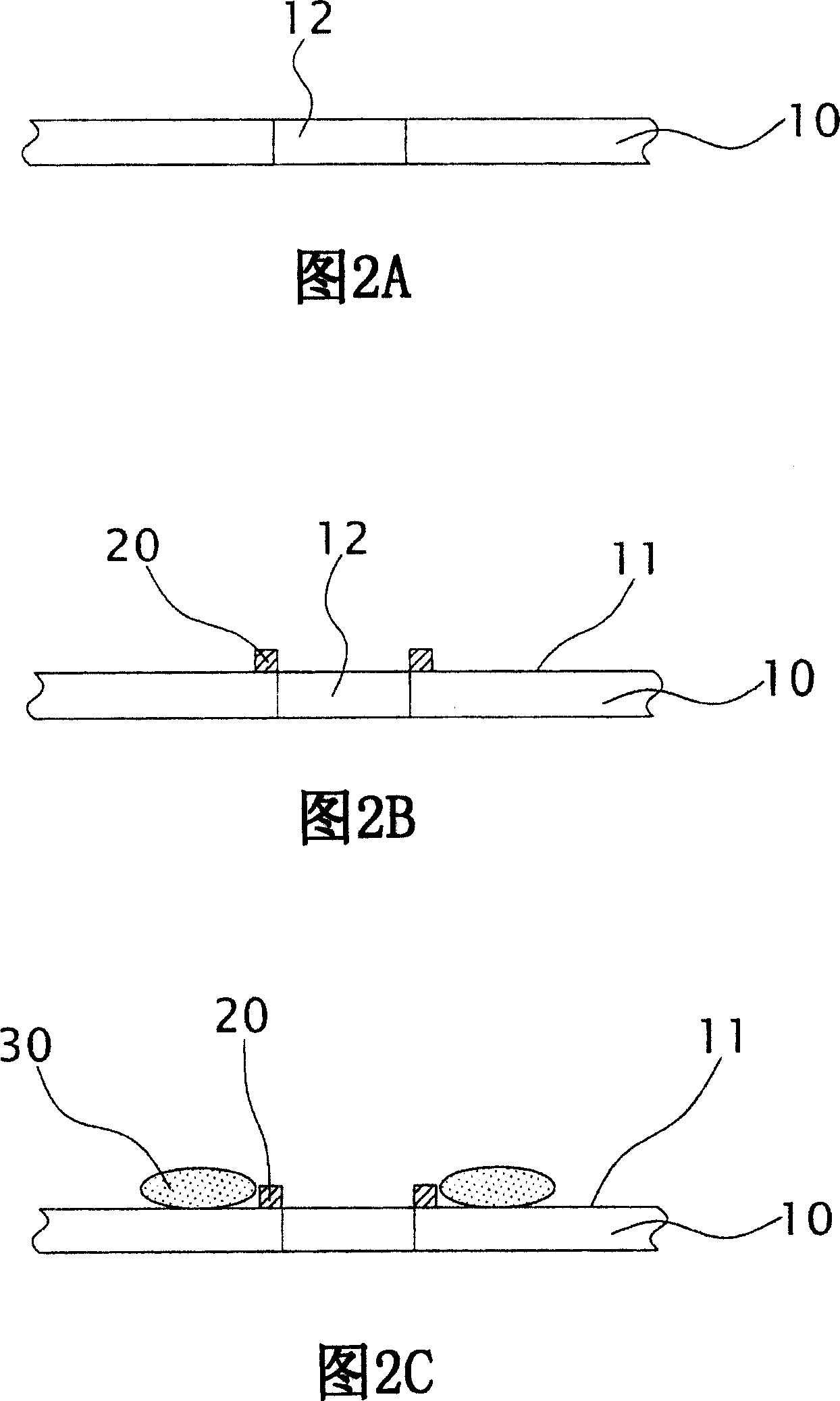
[0035] 2A , 2B, 2C, 2D, 2E, 2F, 2G-1 and 2G-2 are structural cross-sectional views of each step of the chip packaging structure manufacturing method according to an embodiment of the present invention. First, please refer to FIG. 2A, provide a substrate 10, its material is metal, glass, ceramics or polymer material, there is at least one opening 12 through the substrate 10, wherein the substrate 10 can be formed by using a suitable method to form the opening 12 through the substrate 10, or a commercialized structure having at least one opening 12.

[0036] Next, referring to FIG. 2B , a stopper element 20 is formed on the periphery of the opening 12 on the upper surface 11 of the substrate 100 . In one embodiment, the stop member 20 is formed by one of sputtering, vapor deposition, electroless plating and electroplating or by ...


PUM


Abstract

This invention relates to a packaging structure of chips and a manufacturing method including: providing a base board with at least one open-end through it, forming a block element surrounding the open-end of the board, forming an adhering element around the block element, setting a chip on the board and covering the open-end and fixing it with the adhering element on the board, in which, the active surface of the chip is facing to the open-end and part of which exposes it, utilizing a conduction connection element to pass through the open and connect with the active surface of the chip and the bottom surface of the base board electrically and forming a packaging colloid to wrap the element, in which, when the block element is set around the open to resist against adhering the chip, the overflow of the adhering element pollutes the conducting connection points on the active surface of the chip and limits height of the adhering element to reduce the probability of harming the active surface of chips by dust (such as EMC fillers).

Description

technical field [0001] The invention relates to a chip packaging structure and a manufacturing method thereof, in particular to a window-opening type chip packaging structure and a manufacturing method thereof for preventing adhesive overflow. Background technique [0002] With the rapid development of the semiconductor industry, the design of electronic products in IC (integrated) components is developing towards the demand for multi-pin count and multi-function, and the appearance of components is also developing towards the trend of light, thin, short and small. Therefore, the packaging process also faces many challenges, such as the increasingly complex design of the lead frame, the selection of packaging materials, warping of thin packages, heat dissipation and structural strength, etc. These are all problems encountered by the current packaging industry. [0003] The known general windowed ball grid array package structure, as shown in FIG. 1A , is to paste a circuit s...

Claims


Application Information

Patent Timeline
IPC IPC(8): H01L23/488H01L23/12H01L23/31H01L21/50
CPCH01L2224/27013H01L2224/32225H01L2224/48091H01L2224/4824H01L2224/73215H01L2224/83192H01L2224/92147H01L2924/15311H01L2924/00014H01L2924/00
Inventor 陈锦弟
Owner POWERTECH TECHNOLOGY
Why Eureka
Try Eureka