
Rotor of rotating electric machine, rotating electric machine and vehicle drive apparatus

A technology for vehicle drive devices and rotating electrical machines, applied in the field of vehicle drive devices and internal permanent magnet synchronous motors, can solve problems such as increase, achieve high energy efficiency, and reduce iron loss

Inactive Publication Date: 2008-03-05
TOYOTA JIDOSHA KK
View PDF2 Cites 10 Cited by
  • Summary
  • Abstract
  • Description
  • Claims
  • Application Information

AI Technical Summary

Problems solved by technology

If a high rpm motor is used in order to increase the output power density, the effect of iron loss increases to a considerable extent

Method used


Image

  • Rotor of rotating electric machine, rotating electric machine and vehicle drive apparatus
  • Rotor of rotating electric machine, rotating electric machine and vehicle drive apparatus
  • Rotor of rotating electric machine, rotating electric machine and vehicle drive apparatus

Examples


Embodiment Construction

[0039] Hereinafter, the present invention will be described in detail with reference to the accompanying drawings. Hereinafter, the same or corresponding elements are marked with the same reference numerals, and their description will not be repeated.

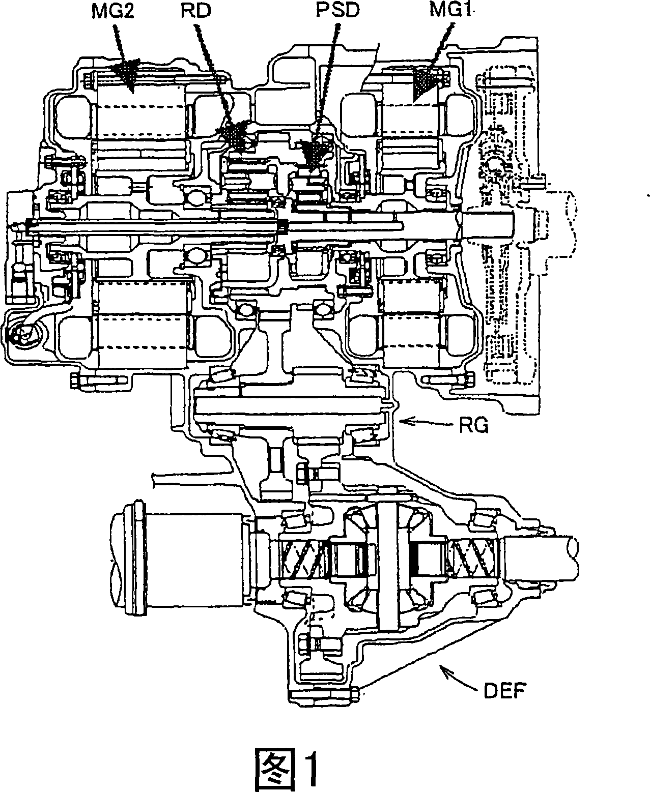
[0040] 1 is a cross-sectional view showing the structure of a vehicle drive device of a hybrid vehicle according to an embodiment of the present invention.

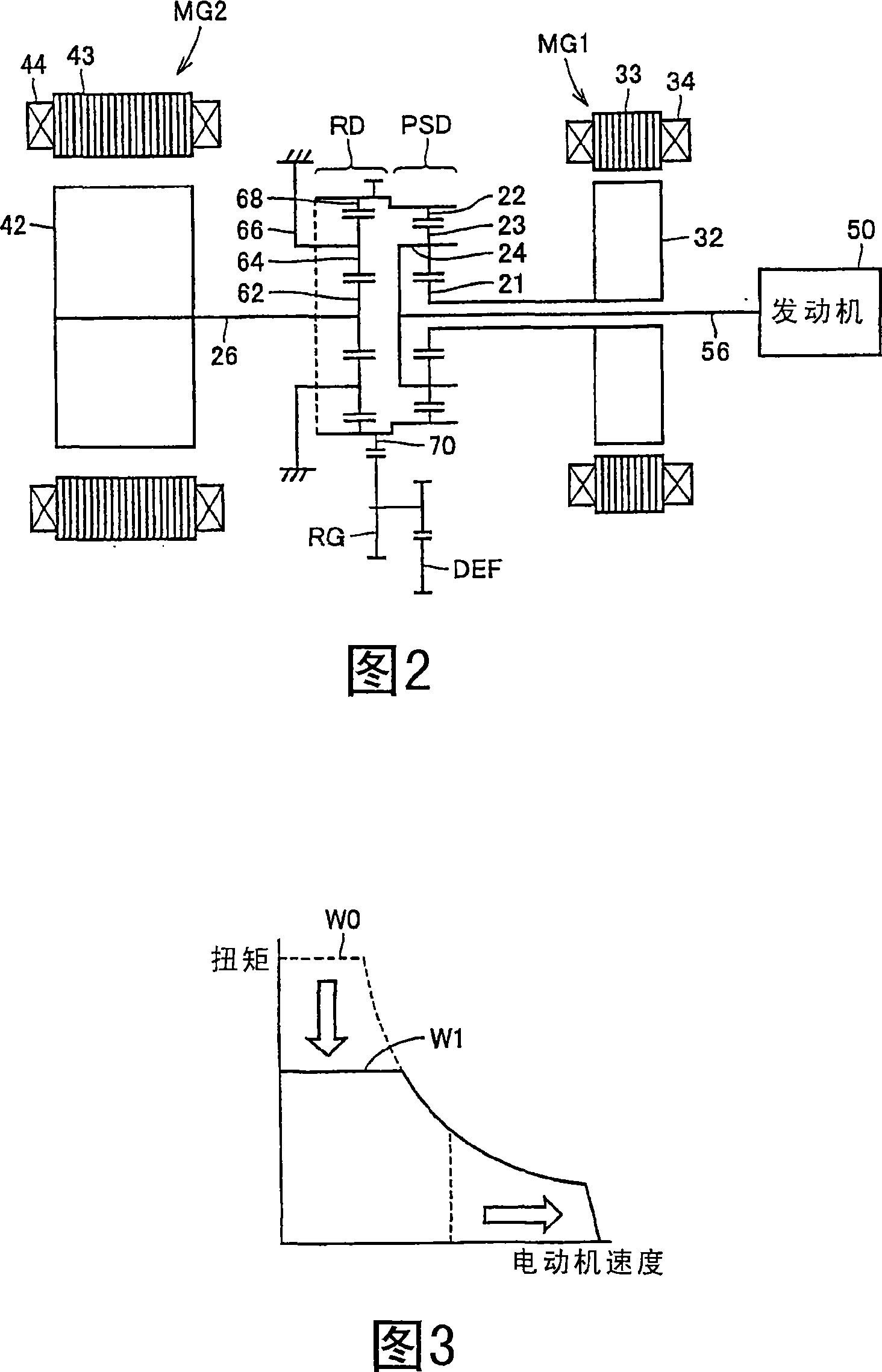
[0041] Referring to FIG. 1, the vehicle drive apparatus includes motor generators MG1 and MG2, a power split device PSD, a reduction mechanism RD, a reduction gear RG, and a differential gear DEF.

[0042] As shown in the cross-sectional view of FIG. 1 , the motor generator MG2 operating mainly as a motor for driving the wheels, the motor generator MG1 operating mainly as a generator, and the power distribution device PSD are arranged in conjunction with the engine (not shown). shown) on the same axis, so that the size of the vehicle drive unit is reduced and the center o...


PUM


Abstract

There are provided a rotor of a rotating electric machine that can implement high-speed rotations with improved energy efficiency, as well as the rotating electric machine and a vehicle drive apparatus. The rotor (42) of the rotating electric machine includes two magnets (90, 92) arranged within an electrical angle in the range of 127 to 140 , the electrical angle having its center at the center of rotations of the rotor, and the magnets being arranged along a V-shape with its acute end facing toward the center of rotations. The rotor further includes a rotor body having two openings (82, 84) housing the two magnets (90, 92) respectively. The rotor body has a support portion (86) placed at the acute end of the V-shape and serving as a partition between the two openings (82, 84).

Description

technical field [0001] The present invention relates to a rotor of a rotary electric machine, a rotary electric machine, and a vehicle drive device. In particular, the present invention relates to an internal permanent magnet synchronous electric machine, a rotor-mounted rotating electric machine, and a vehicle drive. Background technique [0002] Recently, the importance of the role played by electric vehicles in preventing the problem of global warming and saving resources has remarkably increased. For electric vehicles, reducing CO 2 Emissions need to improve fuel economy. Improved fuel economy must come with cleaner emissions and improved safety. [0003] With the improvement of fuel economy of vehicles, fuel cell vehicles as well as hybrid vehicles have received a lot of attention. Components of a hybrid vehicle include a gasoline engine, transmission, inverter, battery, electric motor, and their controllers. These vehicles require highly reliable, efficient, varia...

Claims


Application Information

Patent Timeline
Patent Type & Authority Applications(China)
IPC IPC(8): H02K1/27B60K6/20B60K6/26B60K6/365B60K6/445B60L50/16H02K21/14
CPCY02T10/6239B60K6/26H02K1/2766F16H2037/0866B60K6/365B60K6/445B60L50/61B60L50/16Y02T10/62Y02T10/64Y02T10/7072Y02T10/70
Inventor 神谷宗宏
Owner TOYOTA JIDOSHA KK
Features
  • Generate Ideas
  • Intellectual Property
  • Life Sciences
  • Materials
  • Tech Scout
  • Unparalleled Data Quality
  • Higher Quality Content
  • 60% Fewer Hallucinations
Learn More