Microwave source cathode and manufacturing method therefor

A microwave source and cathode technology, applied in cold cathode manufacturing, electrode system manufacturing, discharge tube/lamp manufacturing, etc., can solve problems such as efficiency affecting the output of microwave sources, short circuit, easy arc generation, etc., and achieve excellent emission and electron emission. Effects of Beam Characteristics

Inactive Publication Date: 2010-04-21
SOUTHEAST UNIV
View PDF2 Cites 0 Cited by
  • Summary
  • Abstract
  • Description
  • Claims
  • Application Information

AI Technical Summary

Problems solved by technology

[0004] The explosive emission cathode has many advantages and is currently the only one that can provide kA / cm 2 Cathodes that emit current density, but they also have serious disadvantages and limitations: 1. The continuous expansion of the surface plasmon as the source of electrons short-circuits the cathode-anode A-K gap, thereby limiting the length (and energy) of the microwave pulse; 2. The pulse width Inside, the waveforms of beam current and voltage often have drastic changes, and the microwave power thus changes drastically
At present, velvet cathodes have been applied in some high-power microwave sources, but their poor vacuum performance, premature gap closure and short service life are bound to be replaced by emerging materials; carbon fiber cathodes use carbon fibers as electronic components. Emitter, the carbon fiber cathode has a lower emission voltage threshold (below 20kV / cm), and has a longer lifespan than metal and velvet cathodes
[0005] At present, even the explosive field emission cathode using carbon fiber still has the disadvantages of severe outgassing and uneven emission. Therefore, before looking for new materials to replace the original cathode materials, we must pay attention to the three main problems that currently exist: 1. Ideal state Under normal circumstances, electrons are emitted from a monoenergetic plasma moving at a low closing speed, but in current practical applications, the plasma is very inhomogeneous and moves at a relatively fast speed; 2. The uniformity and repetition of plasma emission The performance must be guaranteed. The basic solution is to make the emission point as uniform as possible. In practical applications, the asymmetry of the beam current will seriously affect the output efficiency of the microwave source; Otherwise, when the air pressure rises to a certain level, it is easy to generate an arc and cause a short circuit between electrodes. In practical applications, with the increase of power and cathode area, the amount of outgassing will increase significantly.

Method used


Image

  • Microwave source cathode and manufacturing method therefor
  • Microwave source cathode and manufacturing method therefor
  • Microwave source cathode and manufacturing method therefor

Examples


Embodiment 1

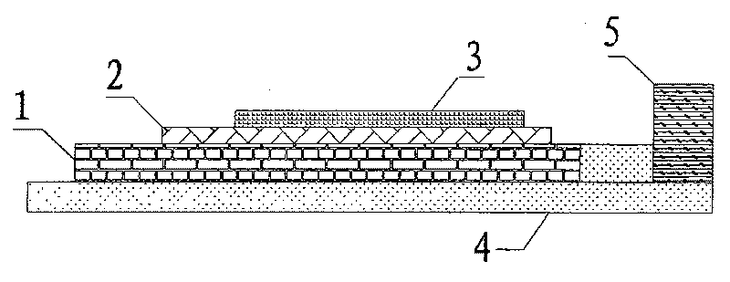
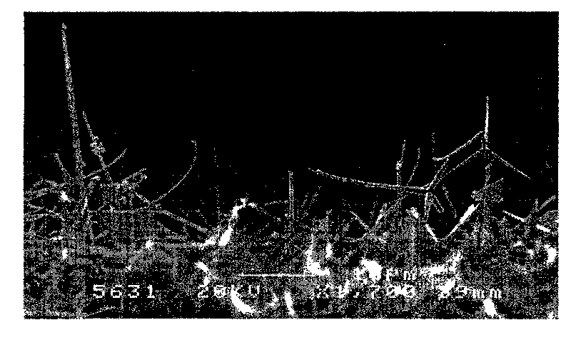
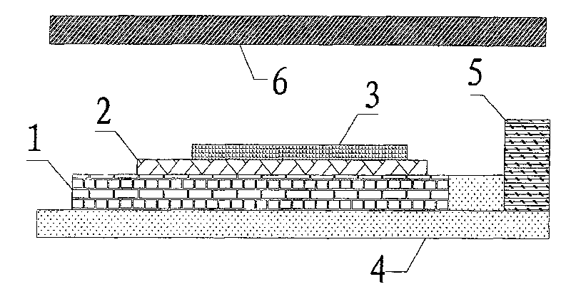
[0027] Embodiment 1: microwave source negative electrode and manufacturing method thereof comprise the following steps: step 1, after mixing 10 grams of four-needle nano-zinc oxide and 100 grams of terpineol in water at 90 degrees Celsius, add an appropriate amount of ethyl cellulose to thicken, and then add 1.1 grams of carbon nanotubes and 2.2 grams of magnesium oxide powder are fully stirred to obtain a slurry; step 2, the slurry in step 1 is printed on the polyacrylonitrile-based activated carbon fiber by screen printing, and the thickness of the slurry is 40 microns; Step 3, as shown figure 2 at 10 -2 After the polyacrylonitrile-based activated carbon fiber in step 2 was baked at a high temperature of 350 degrees Celsius for 3 hours in Pa vacuum, the organic matter in the slurry was decomposed and volatilized, and the method of plasma etching was used to activate the polyacrylonitrile-based activated carbon fiber. Carry out hydrophilic treatment on the carbon fiber surf...

Embodiment 2

[0028] Embodiment 2: microwave source negative electrode and manufacturing method thereof comprise the following steps: Step 1, after mixing 10 grams of four-needle nano-zinc oxide with 1000 grams of terpineol in water at 90 degrees Celsius, add an appropriate amount of ethyl cellulose to thicken, and then add 10.1 grams of carbon nanotubes and 20.2 grams of magnesium oxide powder are fully stirred to obtain a slurry; step 2, the slurry in step 1 is printed on the polyacrylonitrile-based activated carbon fiber by screen printing, and the thickness of the slurry is 400 microns; Step 3, as shown figure 2 at 10 -2 After the polyacrylonitrile-based activated carbon fiber in step 2 was baked at a high temperature of 350 degrees Celsius for 3 hours in Pa vacuum, the organic matter in the slurry was decomposed and volatilized, and the method of plasma etching was used to activate the polyacrylonitrile-based activated carbon fiber. Carry out hydrophilic treatment on the carbon fiber...

Embodiment 3

[0029] Embodiment three: microwave source negative electrode and manufacturing method thereof comprise the following steps: Step 1, after mixing 10 grams of four-needle nano zinc oxide and 500 grams of terpineol in water at 90 degrees Celsius, add an appropriate amount of ethyl cellulose to thicken, and then add 5.1 grams of carbon nanotubes and 10.2 grams of magnesium oxide powder are fully stirred to obtain a slurry; step 2, the slurry in step 1 is printed on polyacrylonitrile-based activated carbon fibers by screen printing, and the thickness of the slurry is 200 microns; Step 3, as shown figure 2 at 10 -2 After the polyacrylonitrile-based activated carbon fiber in step 2 was baked at a high temperature of 350 degrees Celsius for 3 hours in Pa vacuum, the organic matter in the slurry was decomposed and volatilized, and the method of plasma etching was used to activate the polyacrylonitrile-based activated carbon fiber. Carry out hydrophilic treatment on the carbon fiber s...


PUM

PropertyMeasurementUnit
ignition pointaaaaaaaaaa
thicknessaaaaaaaaaa
thicknessaaaaaaaaaa

Abstract

The invention discloses a cathode of microwave source and its manufacturing method, whose electron emission material is carbon fiber fabric and four-stitch nanoparticle ZnO. Mix the four-stitch nanoparticle ZnO with defined amount of terpilenol in the water by whisking, from which the sizing agent obtained can be produced on the carbon fiber fabric by thick film screen printing. Melt abio-flux under high temperature to fix the carbon fiber fabric adhered onto the stainless steel underlay, and weld it with insulated ceramic plate by transition material. The other end of the ceramic plate is welded with a projected auxiliary electrode to improve electric field distribution on the cathode surface and increase the transverse electric field of the cathode surface, which improves the generatingeffieciency of the secondary electron and ensure an even electronic emission of the cathode surface. The said cathode can be taken as the electron source of the high-power microwave source. In practical use for the device, pulsed voltage of hundreds of KV is applied between anode and cathode, while pulsed voltage or DC voltage of 5,000 to 10,000 KV is applied between auxiliary electrode and cathode.

Description

technical field [0001] The invention relates to a microwave source cathode and a manufacturing method thereof. The microwave source cathode can be used as an electron source for high-power microwave source devices, including high-power klystrons, high-power traveling wave tubes, return wave oscillators and relativistic devices, etc., and its application directions are particle accelerators, plasma heating, aerospace communications, etc. . Background technique [0002] The high-power microwave system can use the cathode to generate a high-current electron beam, and the electron beam interacts with the wave in an alternating electromagnetic field to convert the energy of the electron beam into high-power microwave. The high current density cathode is a key component of high power microwave devices. At present, most high power microwave sources use simple non-thermal ionization explosive emission cold cathodes. [0003] The so-called explosive emission means that in the diode...

Claims


Application Information

Patent Timeline
Patent Type & Authority Patents(China)
IPC IPC(8): H01J23/04H01J9/02
Inventor 王琦龙雷威张晓兵朱卓娅殷晓伟
Owner SOUTHEAST UNIV
Why Eureka
Try Eureka