Wire winding bobbin chuck for textile machine

A technology of textile machinery and filament winding drum, which is applied in the field of filament winding drum tube chuck, can solve the problems of affecting the quality of processing, short service life of the chuck, easy wear of the rubber ring, etc., and achieves stable rotation, large friction driving force, Good wear resistance of metal

Active Publication Date: 2008-03-19
李峰
View PDF0 Cites 7 Cited by
  • Summary
  • Abstract
  • Description
  • Claims
  • Application Information

AI Technical Summary

Problems solved by technology

Because the wall thickness of the bobbin is limited, the friction driving force that can be provided to the bobbin is relatively small, which makes the bobbin easy to j

Method used


Image

  • Wire winding bobbin chuck for textile machine
  • Wire winding bobbin chuck for textile machine
  • Wire winding bobbin chuck for textile machine

Examples


Embodiment Construction

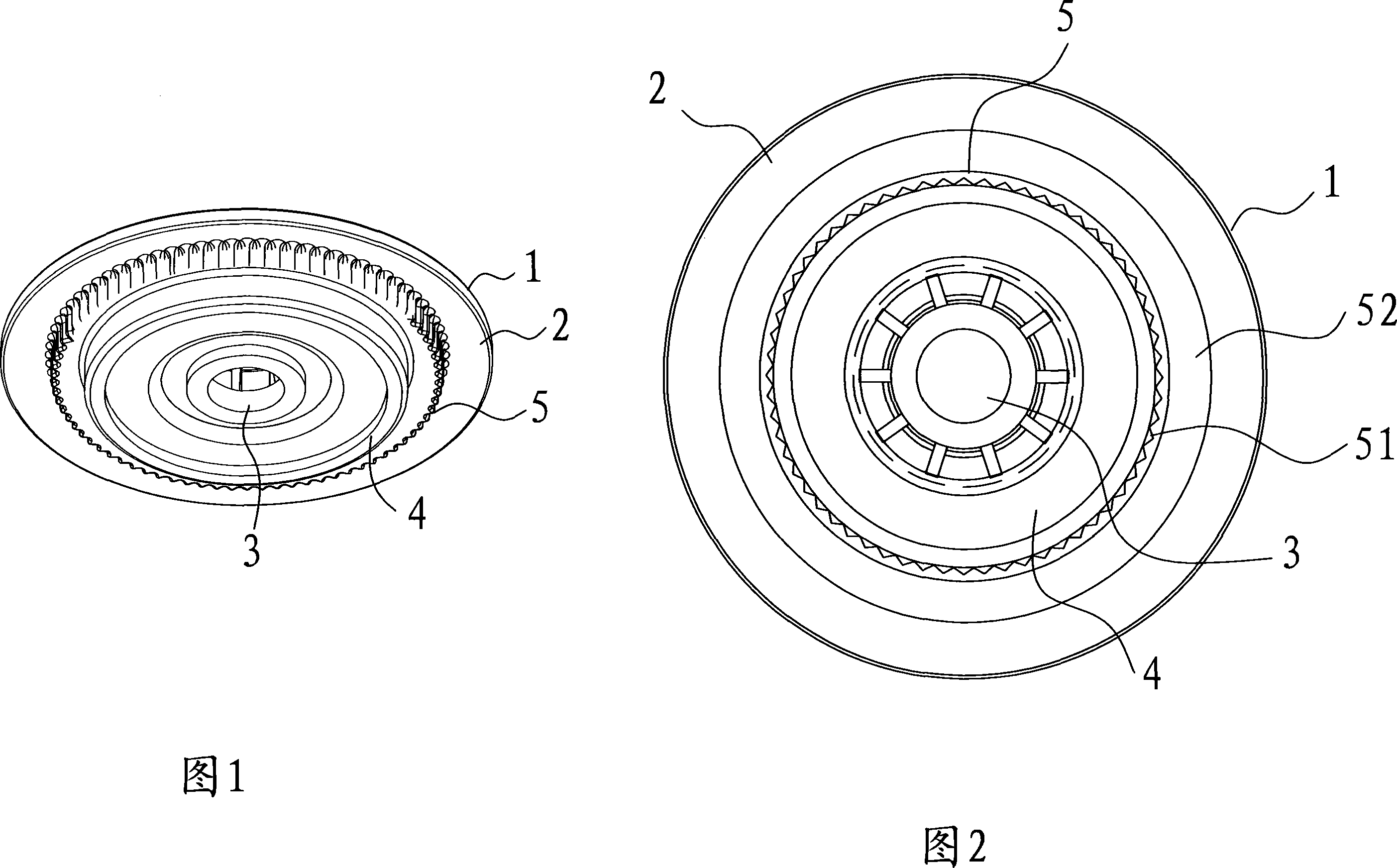
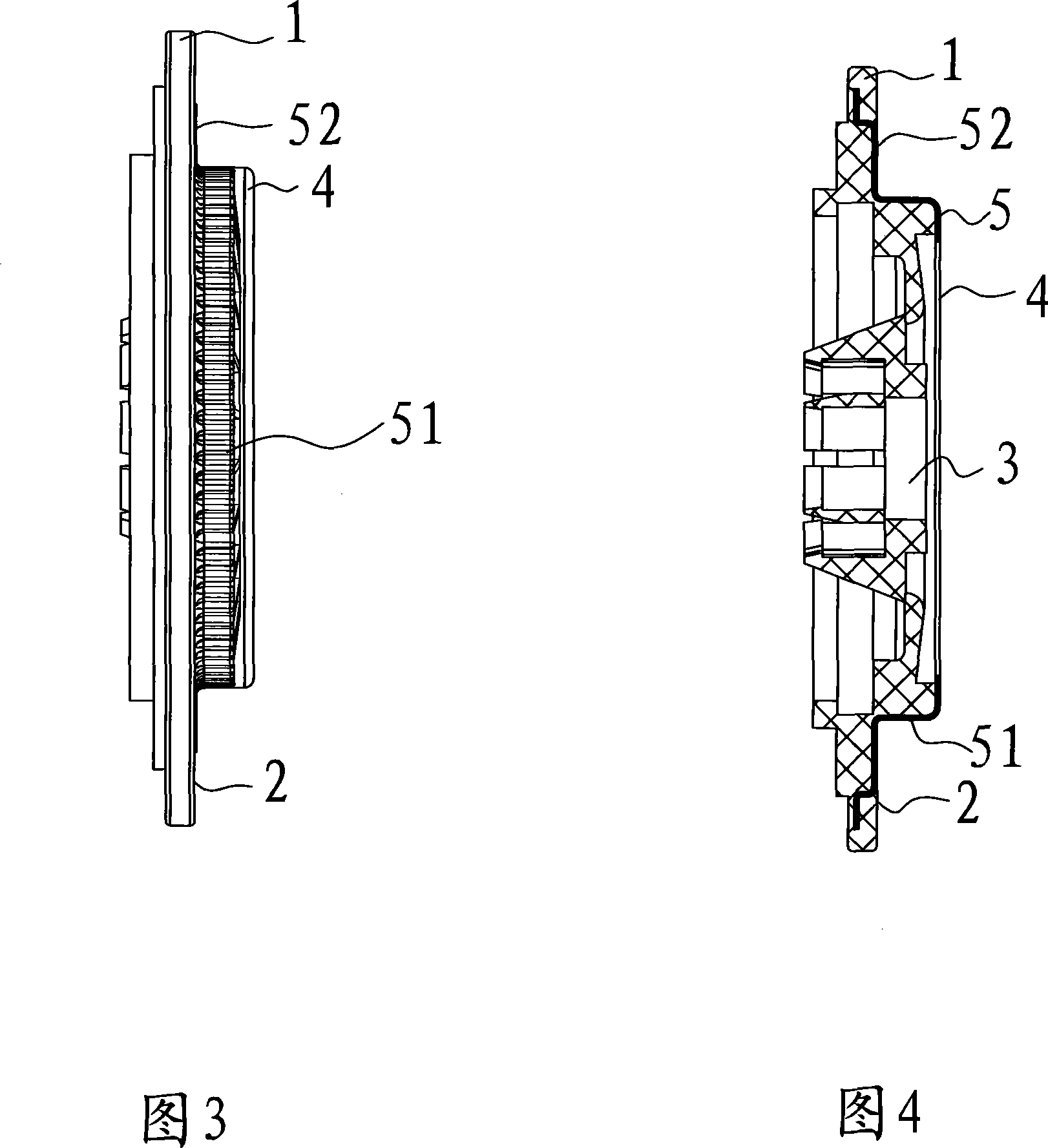
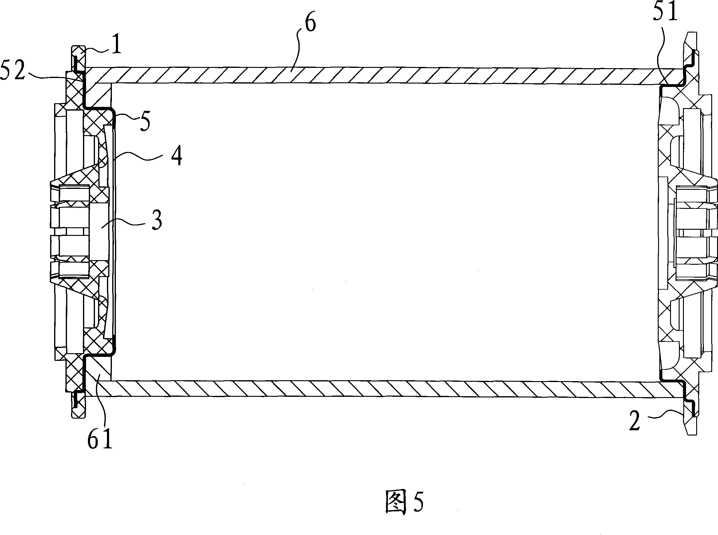
[0018] As shown in Fig. 1, the bobbin chuck on the textile machine includes a disc-shaped disc body 1 made of plastic, a central hole 3 located in the center of the disc body 1 for installing a drive shaft, and a disc body 1 with a The contact end surface 2 that the end surface of the bobbin 8 is in contact with, and the columnar platform 4 axially extending on the contact end surface 2 for cooperating with the inner circle of the bobbin 6, on the outer surface of the columnar platform 4 in the present invention Covered with a metal layer 5 , the metal layer 5 forms an uneven transmission portion 51 on the outer peripheral surface of the columnar platform 4 .

[0019] In order to achieve a better use effect, in this embodiment, the transmission part 51 is evenly arranged in a zigzag shape along the outer circumferential direction of the columnar platform 4, which can generate a larger friction coefficient; and the metal layer 5 and the disc body 1 are integrally arranged , mad...


PUM


Abstract

A winding bobbin chuck on a spinning machine includes a disc-shaped chuck made of plastics, a central hole positioned in the center of the chuck, a contact end face on the chuck which contacts with the end face of the bobbin, a column-shaped bench on the contact end face and capable of matching the inner circle of the bobbin; the outer surface of the column-shaped bench is coated with a metal layer; the metal layer forms an uneven transmission system form the outer circumference surface of the column-shaped bench; large friction driving force can be produced between the transmission system and the bobbin, so that the bobbin runs more stably, and the metal layer is wear resistant, so that the winding bobbin chuck on the spinning machine has quite long service life.

Description

technical field [0001] The invention relates to a chuck for a spinning bobbin on a textile machine, in particular to a chuck for a spinning bobbin in chemical fiber texturizing equipment. Background technique [0002] At present, the two ends of the winding bobbin on the textile machinery are respectively provided with chucks, the end face of the chuck is in contact with the end face of the bobbin, and the contact end face is provided with a columnar platform that can match the inner circle of the bobbin, and the two The cylindrical platform of a chuck is inserted into the inner circle of both ends of the bobbin to fix the bobbin, and a rubber ring is attached to the contact end surface. The rubber ring has lines that can increase friction. Through the friction between the rubber ring and the end surface of the bobbin The bobbin can be driven to rotate. Because the thickness of the tube wall of the bobbin is limited, the friction driving force that can be provided to the bo...

Claims


Application Information

Patent Timeline
IPC IPC(8): B65H54/40
Inventor 李峰
Owner 李峰
Why Eureka
Try Eureka