Pore-pin type cycloid rotor motor

A hole-pin type and rotor technology, which is applied in the direction of rotary piston pumps, rotary piston machines, rotary piston engines, etc., can solve the problem of complex spline connection processing and manufacturing, cycloidal rotor speed can not be high, cycloidal rotor eccentricity Small problems, to achieve the effect of improving mechanical efficiency and service life, increasing output torque, and small flow fluctuations

Inactive Publication Date: 2008-03-19
SHANGHAI NORMAL UNIVERSITY
View PDF0 Cites 6 Cited by
  • Summary
  • Abstract
  • Description
  • Claims
  • Application Information

AI Technical Summary

Problems solved by technology

The disadvantage is that because the cycloid rotor is connected with the output shaft and the distribution shaft by spline coupling, the cycloid rotor eccentricity is small, the displacement is small, the output torque is small, the speed of the cycloid rotor cannot be hig

Method used


Image

  • Pore-pin type cycloid rotor motor
  • Pore-pin type cycloid rotor motor
  • Pore-pin type cycloid rotor motor

Examples


Embodiment 1

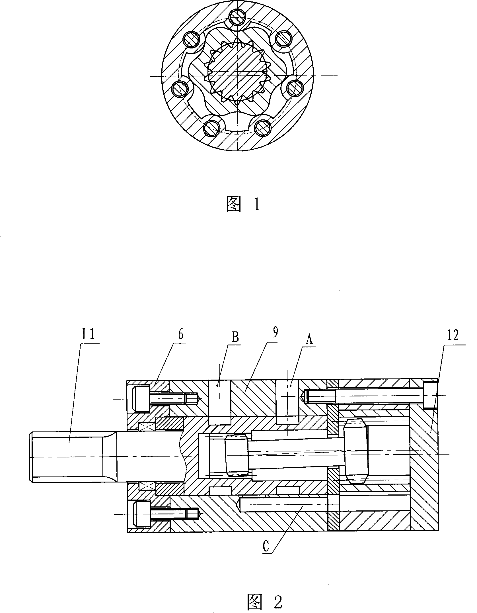
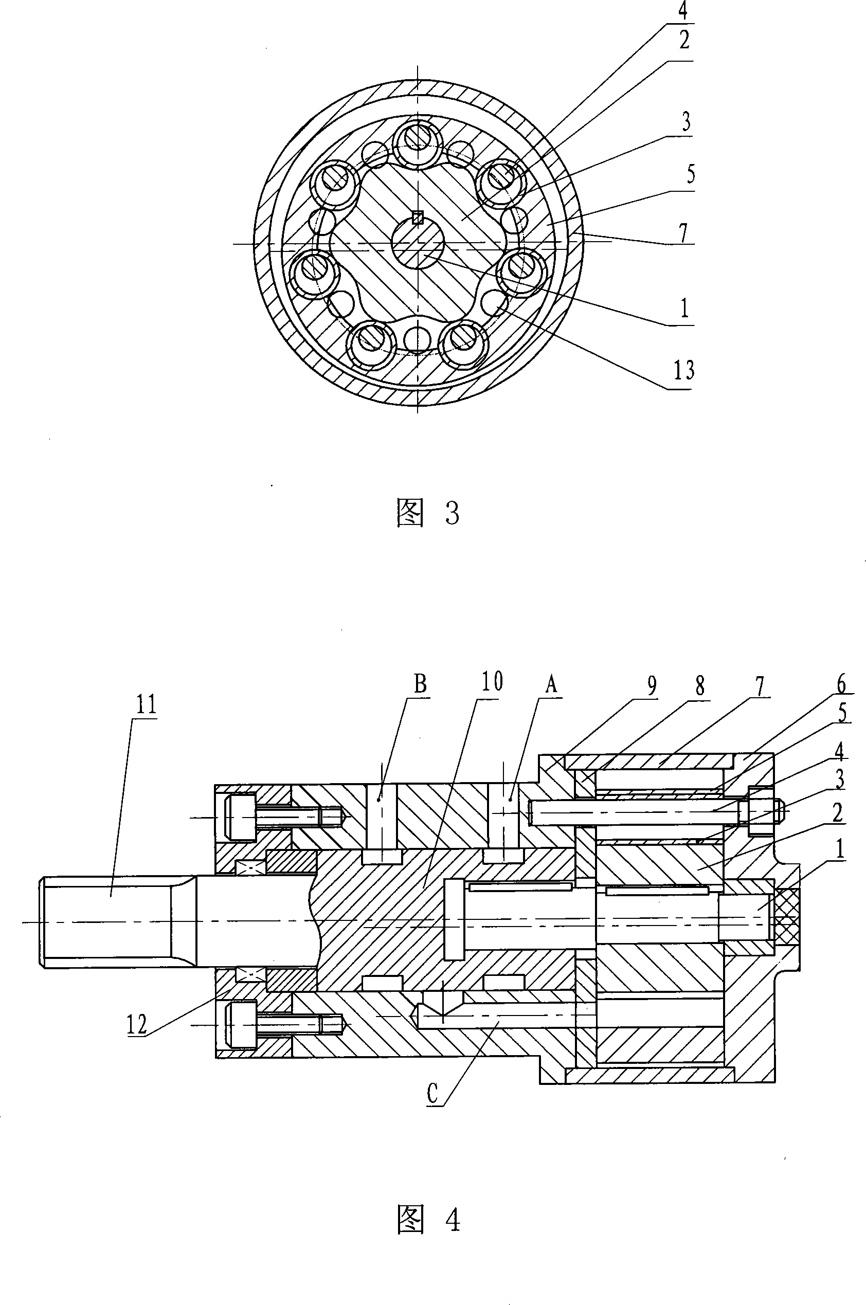
[0045] As shown in Figures 3 and 4, it is mainly composed of the core shaft 1, the inner rotor 2, the sleeve 3, the pin 4, the translation plate 5, the front end cover 6, the housing 7, the backing plate 8, the base 9, and the distribution shaft 10. , The output shaft 11, the rear end cover 12 and other parts. One end of the core shaft 1 is connected with the inner rotor 2 with a coaxial flat key, and the other end is connected with the distribution shaft with a coaxial flat key. The center of the translation disc 5 is a cavity, and seven sleeves 3 are embedded in the inner cavity of the translation disc 5 and form a pin wheel together with the translation disc 5. Seven pins 4 pass through the sleeve 3 and the backing plate 8 and are fixed on the base 9. The diameter of the pin 4 is smaller than that of the sleeve 3. The distribution positions of the sleeve 3 and the pin 4 on the base 9 are the same. The output shaft 11 is coaxially connected with the distribution shaft 10 and the...

Embodiment 2

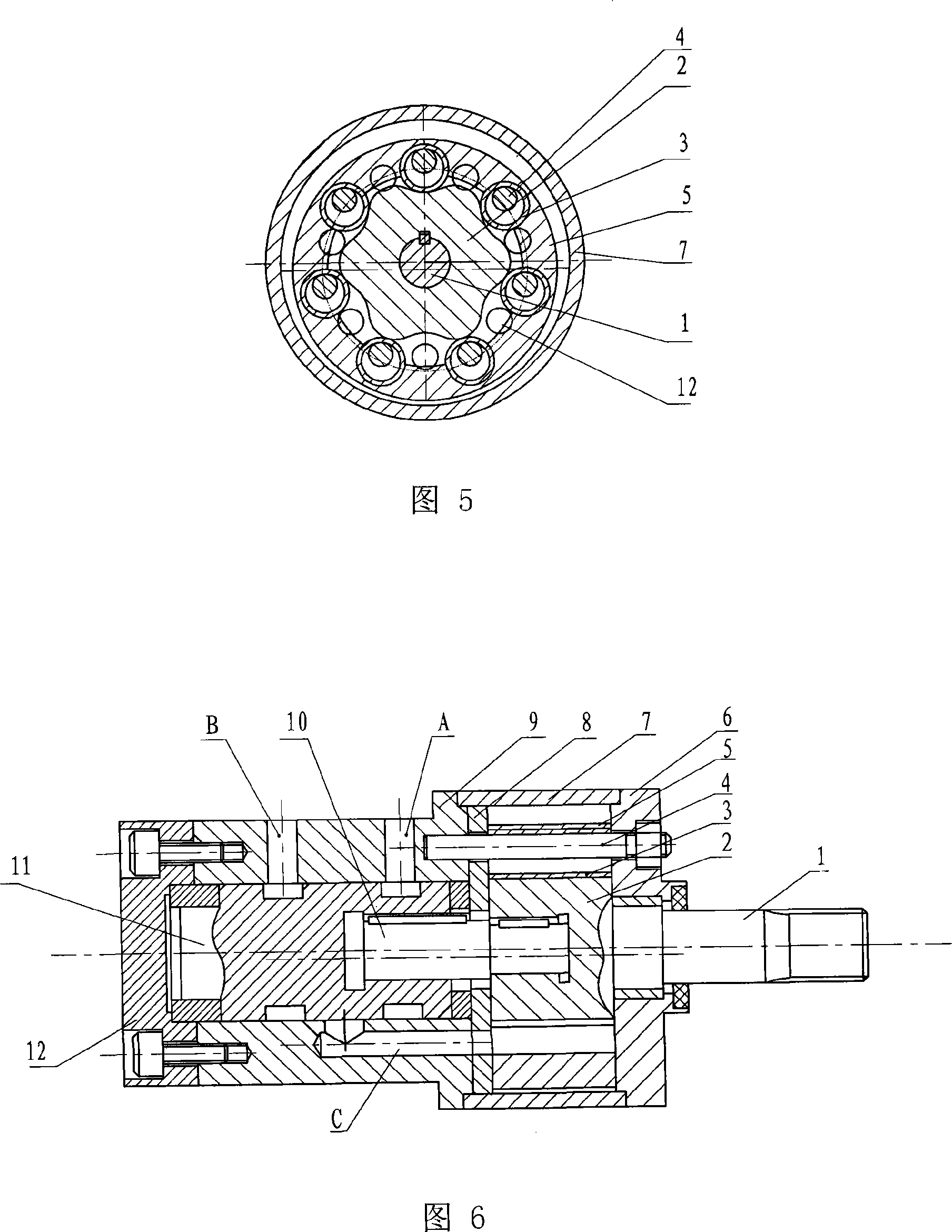
[0049] Its structure is shown in Figures 5 and 6. The output shaft 1 and the inner rotor 2 are coaxially and fixedly connected, and the output shaft 1 directly outputs power from the rotation of the inner rotor 2. This structure generates less torque on the distribution shaft 11 and has less impact on the device and equipment, which is beneficial to the present invention. Maintenance of the life and accuracy of linear rotor motors. The other components and structures are the same as those of the first embodiment, and will not be described in detail.


PUM


Abstract

The invention relates to a hydraulic pressure cycloid rotor type motor structure. A hole pin type cycloid rotor motor, and comprises a front end cover (6), a machine seat (9), a rear end cover (12) and a flow distribution axle (10) positioned at the axle center of the machine seat (9), the invention is characterized in that the flow distribution axle (10) is extended into the casing body (7), and an inner rotator (2) is connected coaxially and fixedly; a short amplitude outer cycloid gear is arranged in the inner rotator (2); a plurality of sleeves (3) are embedded on the inner wall of the central cavity along the parallel operating plate (5); column pins (4) with the same number of the sleeves (3) are respectively penetrated into the sleeves (3), the diameter of the column pin (4) is smaller than the sleeve (3), the column pins (4) are vertically fixed on the machine seat (9) or the end covers (6) and (7), the distribution position on the plane of each column pin is the same as the sleeve (3), and the distance between the parallel operating plate (5) and the casing body (7) is larger than or equals to the diameter difference of the sleeve (3) and the column pin (4). The invention increases the displacement of the hydraulic motor; the torque and the speed are enhanced. The structure is simplified, the manufacturing process is improved, the cost is reduced, and the mechanical efficiency and the service life of the motor are enhanced.

Description

(1) Technical field [0001] The invention relates to a hydraulic transmission motor, in particular to a structure of a cycloid rotor type motor. (2) Background technology [0002] As is known, as shown in Fig. 1 is a planetary cycloid rotor motor of the prior art, which is mainly composed of a distribution shaft, an output shaft, a housing, a spline coupling, a cycloid rotor, a stator, a front and a rear end cover. The tooth profile of the cycloid rotor is a short outer cycloid, and the stator tooth profile is an arc. Has Z 1 The cycloidal rotor with three teeth, that is, the pinion with external teeth, and has Z 2 The stator with two teeth, namely the inner ring gear meshes, forming Z 2 A closed volume. These closed volumes are connected to the inlet and outlet ports through the valve shaft. The valve shaft acts as a switching valve to control the connection or disconnection between the oil inlet and outlet ports and each closed volume. 2 Nearly half of the enclosed volume is in ...

Claims


Application Information

Patent Timeline
IPC IPC(8): F03C2/08F04C2/10
Inventor 林菁
Owner SHANGHAI NORMAL UNIVERSITY
Why Eureka
Try Eureka