Sanitary liquid electrical heating tank

A technology of electric heating and electric heater, which is applied in the field of sanitary liquid heating, can solve the problems of reduced heat transfer efficiency, difficulty in cleaning, and rise in operating temperature of electric heating tubes, and achieves low manufacturing cost, simple assembly process, and prevention of dry burning without water Effect

Inactive Publication Date: 2008-03-19
黄樟焱
View PDF0 Cites 0 Cited by
  • Summary
  • Abstract
  • Description
  • Claims
  • Application Information

AI Technical Summary

Problems solved by technology

[0006] 1. Difficult to clean
After the water dispenser is used for a period of time (the length of time is related to the water quality), scale will form on the outer wall of the electric heating tube and the inner wall of the tank, which will affect the water quality
In addition, the scale on the electric heating tube will also reduce the heat transfer efficiency, and the operating temperature of the electric heating tube will increase, which will affect the service life of the electric heating tube
Therefore, it is necessary to clean the hot tank, and the stainless steel tank body is a non-detachable structure and cannot be disassembled for cleaning
The usual method is to pour an acidic solution (such as citric acid) into the hot tank to dissolve the scale on the electric heating tube, but the effect is not ideal
[0007] 2. Cannot be repaired
If the electric heating tube has been used for a long time, or there is no water and dry burning, the electric heating tube will be damaged, and the water dispenser will not work normally.
Since the stainless steel tank cannot be disassembled, the electric heating tube and the stainless steel tank can only be scrapped together during maintenance, and then replaced with a new heating tank, which is a great waste
[0008] 3. The seal is unreliable, and leakage often occurs
[0009] 4. Water quality is difficult to guarantee
[0010] 5. Poor insulation performance and large heat loss
In order to reduce costs, hot tanks usually use low-density foam as the insulation layer, which has a poor insulation effect
The water dispenser is usually heated by the electric heating tube every 20 to 40 minutes. This repeated heating not only wastes electric energy but also deteriorates the water quality.

Method used


Image

  • Sanitary liquid electrical heating tank
  • Sanitary liquid electrical heating tank
  • Sanitary liquid electrical heating tank

Examples


Embodiment 1

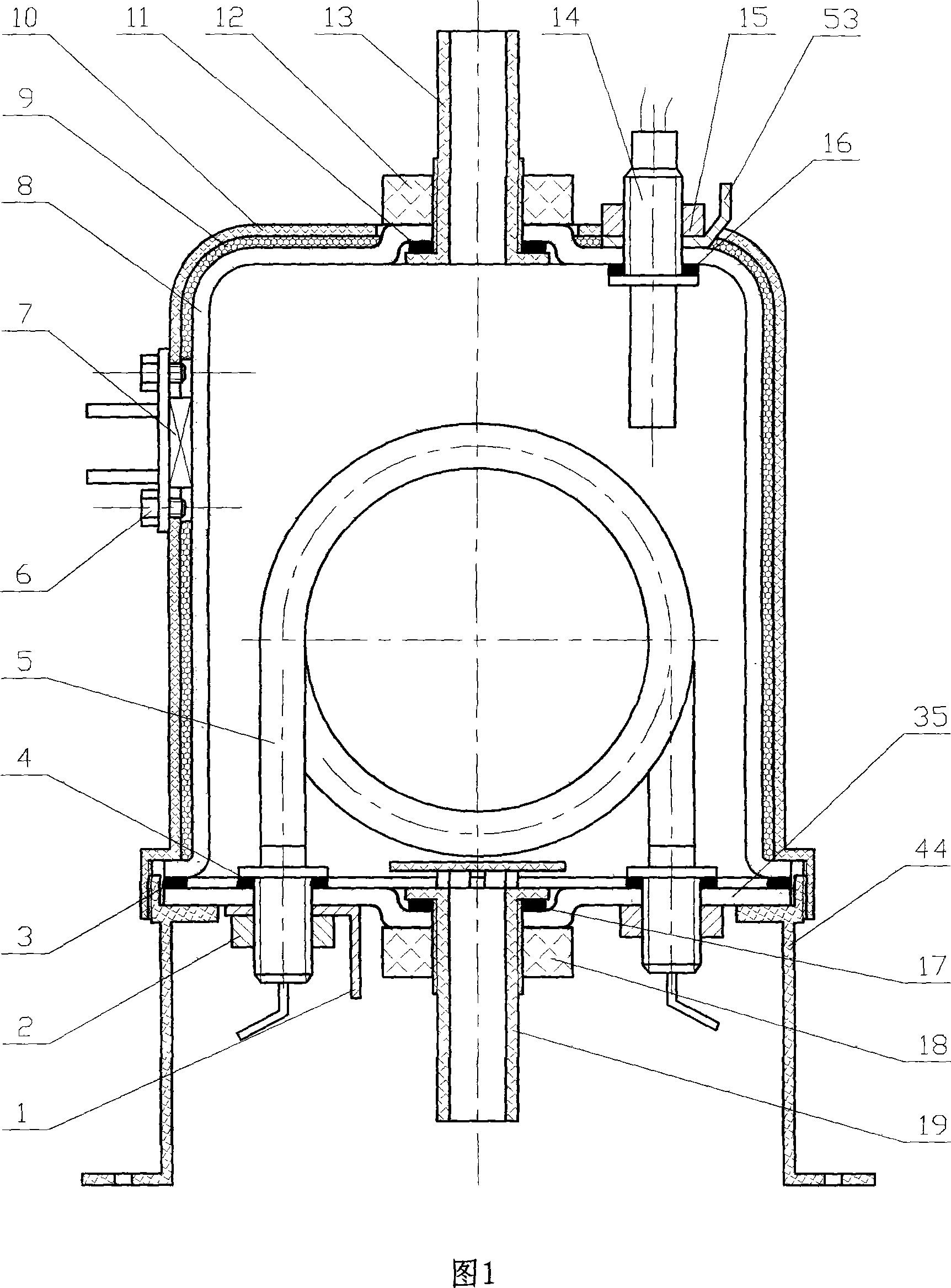
[0045] Embodiment one: in conjunction with Fig. 1 and shown in Fig. 2, the tank body of hot pot adopts purple sand pottery material to make, and tank body comprises upper tank body (8) and lower bottom (35) two parts, in upper tank body (8) and The joint of the lower bottom (35) is provided with a sealing ring (3), and the top of the upper tank body (8) is provided with an opening for installing a water outlet exhaust pipe (13) and a temperature measuring probe (14), which are close to the upper tank body The side wall of (8) is provided with manual reset thermostat (7), and bottom (35) is provided with the opening that can assemble electric heating tube (5) and water inlet and drain pipe (19); The outside of described tank body is provided with The shell, the shell includes two parts, the upper shell (10) and the lower shell (44), the upper shell (10) and the lower shell (44) are threadedly connected, the bottom of the upper shell (10) is provided with internal threads, and th...

Embodiment 2

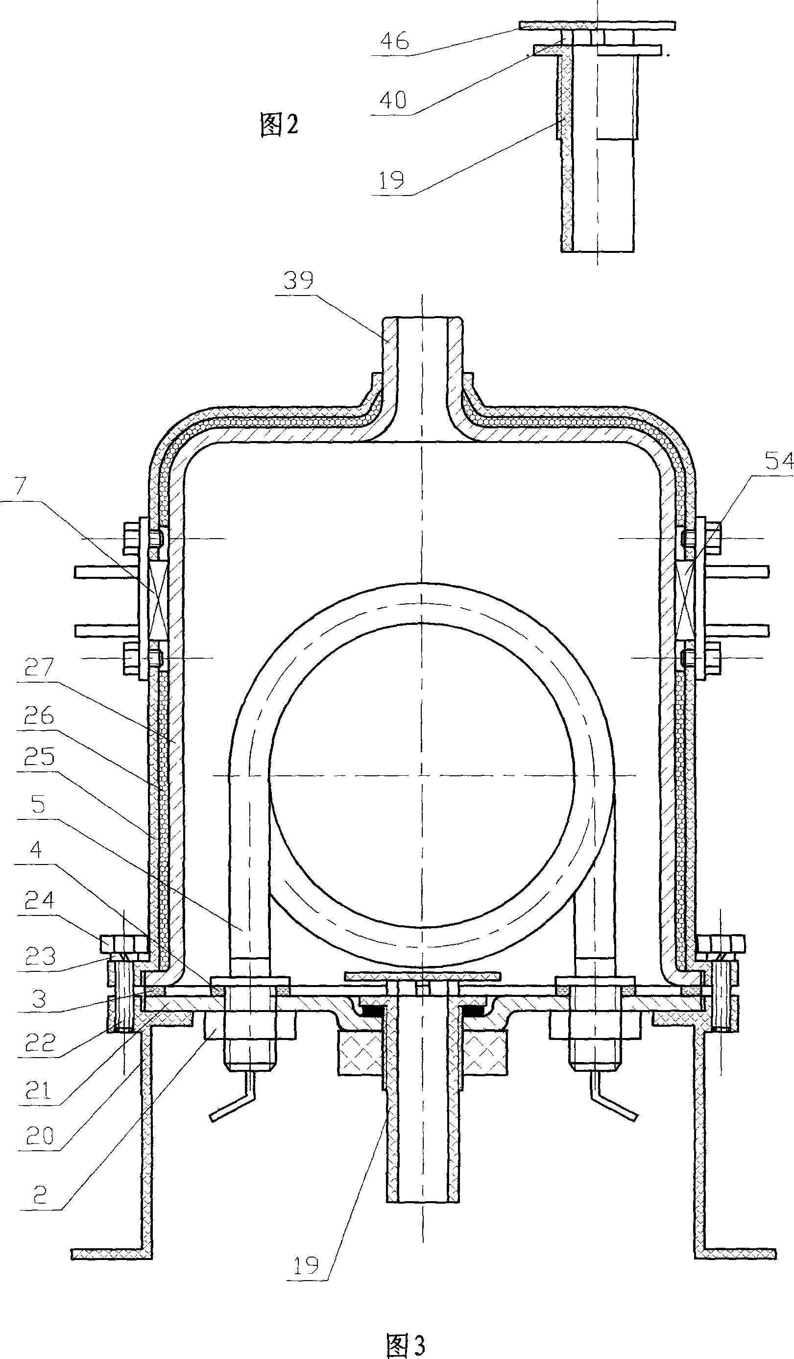
[0046] Embodiment two: in conjunction with shown in Fig. 3, the tank body of heat tank adopts heat-resistant glass to make, and tank body comprises upper tank body (27) and lower bottom (21) two parts, in upper tank body (27) and lower bottom ( 21) is provided with a sealing ring (3) at the joint, the top of the upper tank (27) is provided with a water outlet exhaust pipe (39), and the side wall of the upper tank (27) is provided with a manual reset thermostat ( 7) and an automatic reset thermostat (54), the lower bottom (21) is provided with an opening that can be assembled with a water inlet and drain pipe (19) and an electric heating tube (5); the outside of the tank body is provided with a shell, and the shell includes The upper shell (25) and the lower shell (20) are two parts, the upper shell (25) and the lower shell (20) are fixedly connected by screws (24) and washers (23), the upper shell (25) and the lower shell (20) The connecting part is provided with screw holes, ...

Embodiment 3

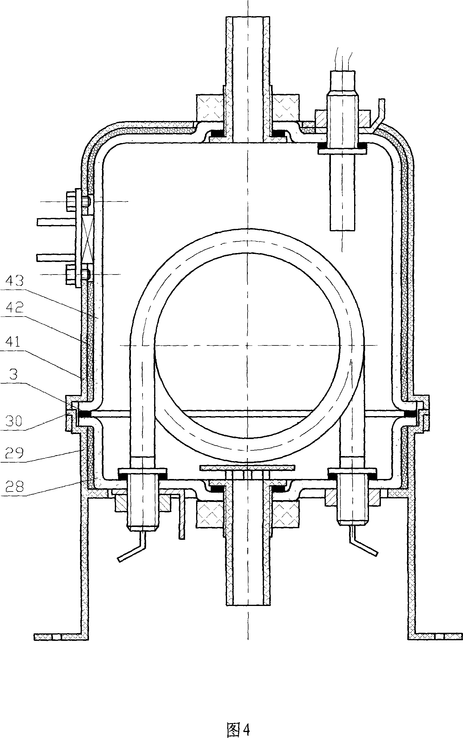
[0047] Embodiment three: in conjunction with shown in Fig. 4, the tank body of hot pot adopts porcelain material to make, and tank body comprises upper tank body (43) and lower tank body (28) two parts, in upper tank body (43) and lower tank body The junction of (28) is provided with sealing ring (3); The outside of described tank body is provided with shell, and shell comprises upper shell (41) and lower shell (29) two parts, upper shell (41) and lower shell ( 29) It is connected by buckle, the lower part of the upper shell (41) is provided with a bayonet, the upper part of the lower shell (29) is provided with a locking tooth (30), and the locking tooth (30) of the lower shell (29) is snapped into the upper shell After the bayonet joint of (41), upper tank body (43) and lower tank body (28) can be connected into one, and sealing ring (3) can be compressed to keep the joint surface in a sealed state; Insulation layer (42) is arranged. Other requirements of this embodiment ar...


PUM


Abstract

The invention provides a sanitary fluid electric heating pot. A water outlet opening and a water inlet opening are arranged on the pot body of the electric heating pot, an electric heater is arranged in the pot body, the pot body consists of two parts which are connected through a detachable structure, a seal ring is arranged at the connecting position, and the pot body is made from nonmetal material. The invention is mainly used for heating the drinking water on a water dispenser, and also can be used for heating sanitary fluid on the similar products. Compared with the heating pot of the water dispenser in the prior art, the invention has the advantages that the water quality is ensured, the washing is convenient, the maintenance is easy, the seal is reliable, the assembly is simple, the heat preservation performance is good, and the production cost is not high.

Description

technical field [0001] The invention relates to the technical field of sanitary liquid heating, in particular to an electric heating tank for sanitary liquid which can be used in drinking water dispensers to heat drinking water. Background technique [0002] Along with the raising of people's living standard, the use of water dispenser is very popular now. The hot tank in the water dispenser is usually made of stainless steel, and its heating method is designed as an internal heating type or an external heating type. [0003] The externally heated hot tank structure is to install the electric heater on the outer surface of the stainless steel tank body. The biggest defect of this design method is that it emits more heat to the environment, the utilization rate of heat energy is low, and the manufacturing cost is high. , has now been largely eliminated. [0004] The internal heating type heat tank structure is adopted, and the electric heating tube is placed in the stainles...

Claims


Application Information

Patent Timeline
IPC IPC(8): F24H1/20F24H9/18F24H9/20
Inventor 黄樟焱黄瑞中
Owner 黄樟焱
Why Eureka
Try Eureka