Heat pipe structure

A heat pipe and structure technology, used in indirect heat exchangers, lighting and heating equipment, etc., can solve problems such as difficulty in achieving power generation, excessive distance between magnet rings and power output coils, etc.

Inactive Publication Date: 2008-03-19
SUZHOU FORCECON ELECTRIC
View PDF0 Cites 4 Cited by
  • Summary
  • Abstract
  • Description
  • Claims
  • Application Information

AI Technical Summary

Problems solved by technology

[0006] The purpose of the present invention is to provide a heat pipe structure. The purpose of the present invention is to solve the problem that the distance between the magnet ring and the power

Method used


Image

  • Heat pipe structure
  • Heat pipe structure
  • Heat pipe structure

Examples


Embodiment

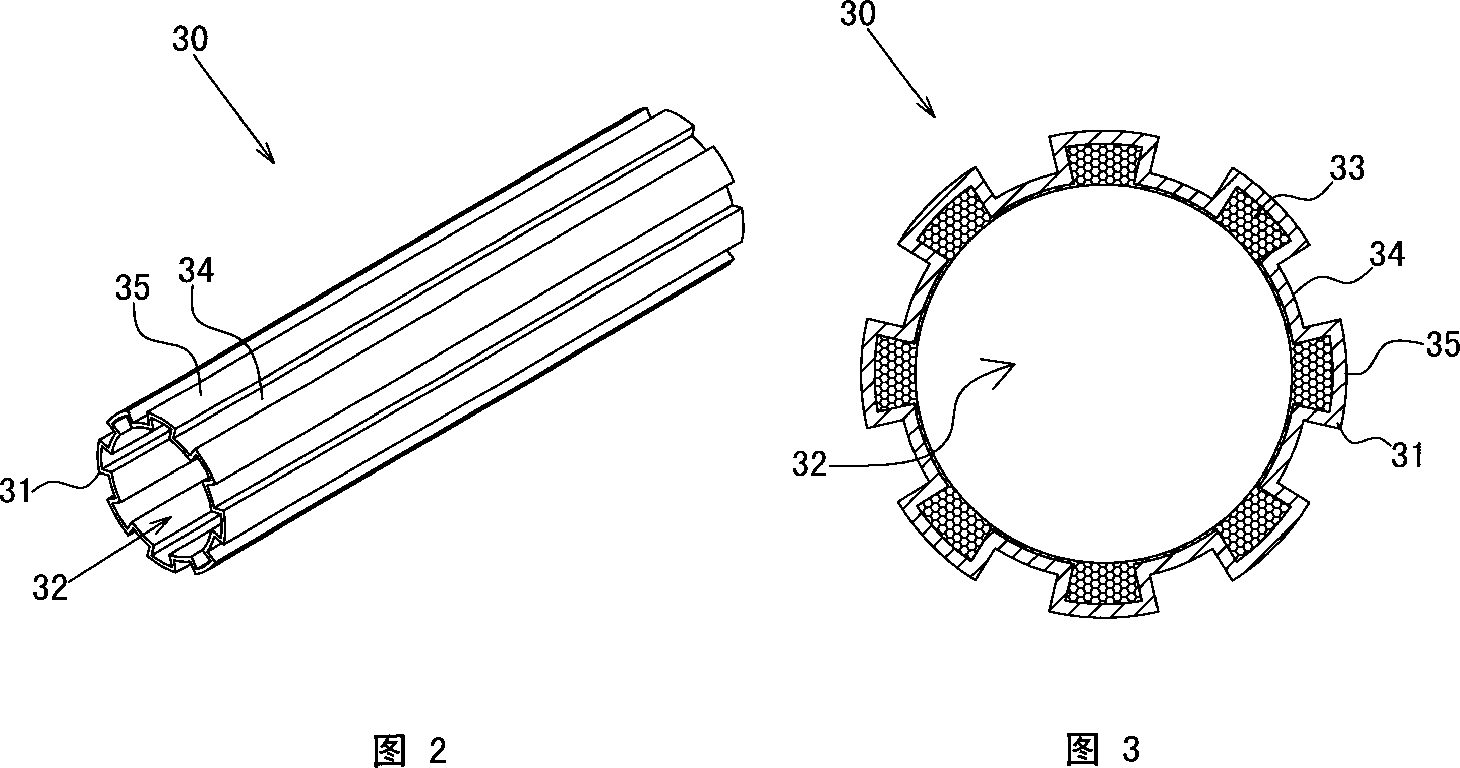
[0028] Please refer to Figures 2 to 3, which are preferred embodiments of the heat pipe structure of the present invention,

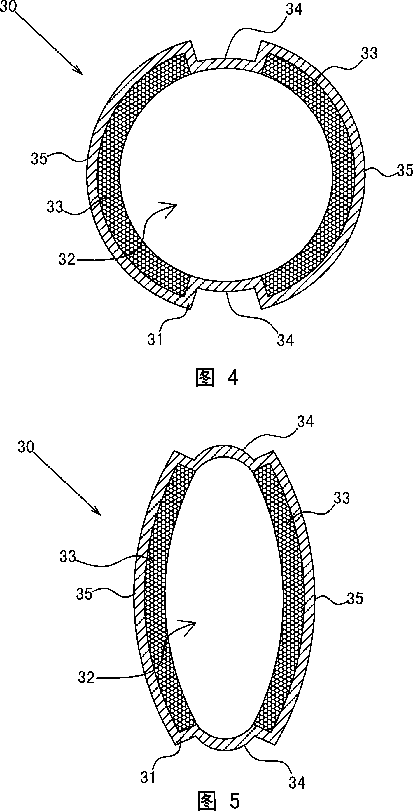
[0029] The heat pipe 30 is a hollow tube body with both ends closed, including a tube wall 31 and a hollow tube groove 32, the inner side of the tube wall 31 is provided with capillary tissue 33, and the inside of the hollow tube groove 32 is in a vacuum state and Filled with working fluid (please refer to the state of the heat pipe shown in FIG. 8 ), the pipe wall 31 of the heat pipe 30 is concave-convex and wrinkled, and a plurality of concave edge portions 34 and flange portions 35 are formed.

[0030] Wherein, as shown in Figure 2, the concave edge portion 34 and the flange portion 35 can be distributed in the structural form of the entire section of the heat pipe 30 wall 31, or the heat pipe 30 as shown in Figure 5, the concave edge portion 34B and the flange portion 35B are structural forms distributed in a local section of the tube wall 31 of the...


PUM


Abstract

The invention provides a heat pipe structure. The heat pipe comprises a pipe wall and a hollow pipe groove, and a capillarity organization is arranged on the inner side of the pipe wall. The invention is characterized in that the heat pipe wall presents a concavo convex buckling shape and forms a plurality of concave margin and flange parts; and the heat pipe can be provided with a generator, the heat pipe comprises an electrical output coil arranged on the outer side of the heat pipe wall and a magnetic iron ring arranged in the hollow pipe groove, a rotor and an impeller, therefore, the electrical output coil can be inserted on the concave margin part of the heat pipe wall, the capillarity organization can be inserted in a depressed space formed by the inner side of the concave margin part, thus the space of the electrical output coil and the magnetic iron ring can be smaller, thereby to effectively improving a power generation effect, and the capillarity organization can still have the enough thickness, and the heat conducting efficiency is not influenced.

Description

technical field [0001] The invention relates to a heat pipe structure, in particular to an innovative design in which the pipe wall is concave-convex and wrinkled, and concave and flange parts are formed. Background technique [0002] The existing heat pipe is usually a hollow pipe body with a circular section or a flat section, and in order to improve the heat conduction effect of the heat pipe, the inner wall of the pipe is provided with capillary tissue. [0003] The above existing heat pipes still have the following problems in practical application: [0004] When the heat pipe structure is combined with a generator, as shown in FIG. Hollow inside, that is, the magnet ring 12 and the power output coil 11 of the generator 10 are separated by the tube wall of the heat pipe 20, wherein, because the thickness of the outer wall of the heat pipe 20 is about 0.3-0.5mm, and the thickness of the inner capillary tissue 21 Thicker, about 0.5~1mm, so the thickness of the two added...

Claims


Application Information

Patent Timeline
IPC IPC(8): F28D15/04
Inventor 饶振奇何信威
Owner SUZHOU FORCECON ELECTRIC
Why Eureka
Try Eureka