Power factor correction circuit

A technology of power factor correction and power factor correction, which is applied in the field of power factor correction circuits, can solve problems such as peak high voltage, achieve the effect of reducing costs and meeting the requirements of electrical clearance and creepage distance

Inactive Publication Date: 2008-03-19
SHENZHEN TCL NEW-TECH CO LTD
View PDF0 Cites 4 Cited by
  • Summary
  • Abstract
  • Description
  • Claims
  • Application Information

AI Technical Summary

Problems solved by technology

This will cause a high peak voltage between the primary and secondary pins of the SMT components of the switching power supply

Method used


Image

  • Power factor correction circuit
  • Power factor correction circuit

Examples


Embodiment Construction

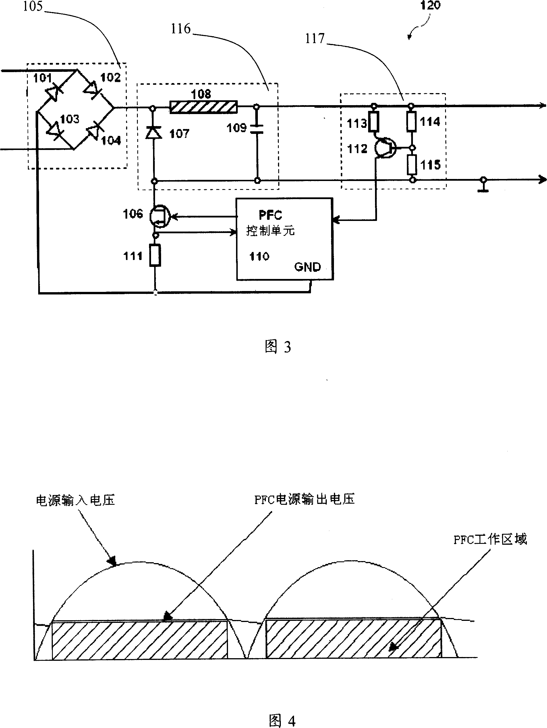
[0012] Please refer to FIG. 3 , which is a circuit diagram of the step-down regulator circuit of the present invention. The circuit includes a power supply (mains) rectifier 105 with four diodes 101, 102, 103, 104, a switch 106, a detection resistor 111, a step-down circuit 107 with a diode 107, an inductor 108, and a capacitor 109, a transistor 112 and three A current source 117 of resistors 113, 114, 115. The switch 106 and the transistor 112 can be bipolar transistors or MOS transistors. In this embodiment, the switch 106 is a MOS transistor, and the transistor 112 is a bipolar transistor.

[0013] In this circuit, one end of the inductor 108 is connected to the cathode of the diode 107 , and the other end is connected to one end of the capacitor 109 . The other end of the capacitor 109 and the anode of the diode 107 are both connected to the drain of the switch 106, the cathode of the diode 107 is also connected to one end of the power rectifier 105, and the ground pin of...


PUM


Abstract

The invention discloses a power-factor correcting circuit, which comprises an input terminal for a receiving input AC power supply, an output terminal for supplying output DC power supply, a power rectifier connected with the input terminal, a voltage step-down circuit connected with the power rectifier and providing the output voltage to the output terminal, and a switch connected with the voltage step-down circuit. The circuit also comprises a current source circuit for generating a current signal based on the voltage value; a detection resistor connected with the switch and used for generating a voltage signal based on the current value passing through the switch; and a power-factor correction unit for receiving the voltage signal and the current signal and controlling the switch based on the relation of the input voltage and the output voltage to make the voltage step-down circuit selectively run or not run. The invention can provides lower input voltage for a switching power supply, manufacture smaller elements, and further reduce cost, and is easier to meet the requirement of electric clearance and creepage distance.

Description

technical field [0001] The invention relates to a power factor correction circuit, in particular to a power factor correction circuit capable of generating low DC power AC voltage. Background technique [0002] In the prior art, a PFC (Power Factor Correction, power factor correction) function usually generates a DC output voltage of about 400V. The output voltage is generally used as an input voltage of a switching power supply (SMPS) in the next stage of the PFC circuit. Surface Mount Technology (SMT) is a technology that directly mounts electronic components on the surface of Printed Circuit Boards (PCB) to build circuits. When a switching power supply as an SMT component is supplied with a high DC voltage, the maximum voltage between its primary and secondary pins is usually higher. Due to the high voltage between the primary and secondary pins of SMT chips, large-sized SMT components must be separated from other components by a long distance. [0003] In order to kee...

Claims


Application Information

Patent Timeline
Patent Type & Authority Applications(China)
IPC IPC(8): H02J3/18H02M1/14
CPCH02M1/4208Y02B70/126H02M2001/4291H02M1/4291Y02B70/10
Inventor 考格尔·莱因哈德卢伏·吉恩.保罗梅特兹南·迈克尔
Owner SHENZHEN TCL NEW-TECH CO LTD
Why Eureka
Try Eureka