Passive combined multi-purpose thimble device

A multi-purpose, thimble technology, used in electrical components, electrical components and other directions, can solve the problems of unstable work, insufficient support density, and the inability of the placement machine to meet the requirements, and achieve the effect of strong versatility

Inactive Publication Date: 2008-03-19
杨建华
View PDF0 Cites 7 Cited by
  • Summary
  • Abstract
  • Description
  • Claims
  • Application Information

AI Technical Summary

Problems solved by technology

These three types of thimble devices have their own advantages and disadvantages, and their application ranges are also different, but they have a common disadvantage, that is, they cannot meet the requirements of various products in terms of supporting high-density double-sided printed circuit boards.
The specific points are as follows, the hard thimble, the thimble is mainly made of steel or aluminum alloy, which is characterized by a large supporting force and is suitable for supporting relatively flat products, such as stencil printing, which cannot be satisfied for placement machines. The working requirements of the uneven circuit board; air thimble, the thimble is mainly made of steel or aluminum alloy, but the surface of the thimble is soft. When working, the ejector rod is in contact with the printed circuit board and locked by the principle of pneumatics. Its supporting force is suitable for the requirements of double-sided printed circuit boards, and it is the most widely used thimble device at present, but it has the following disadvantages, one is that the support density is not enough, and the other is that the versatility is not strong. , can only be applied to several similar printed circuit board dimensions, and because of the high cost of the gas thimble, it is easy to cause air leakage during work
The soft thimble is made of rubber, and the printed circuit board components are attached to the top of the rubber thimble when it is working. Its advantage is low cost and suitable for flat circuit board support. Its disadvantage is that the size of the components on the support surface is not consistent. When it is used, the force on the printing plate is obviously uneven, resulting in the problem of unstable work

Method used


Image

  • Passive combined multi-purpose thimble device
  • Passive combined multi-purpose thimble device
  • Passive combined multi-purpose thimble device

Examples


Embodiment Construction

illustration:

[0020] 1. Ejector unit;

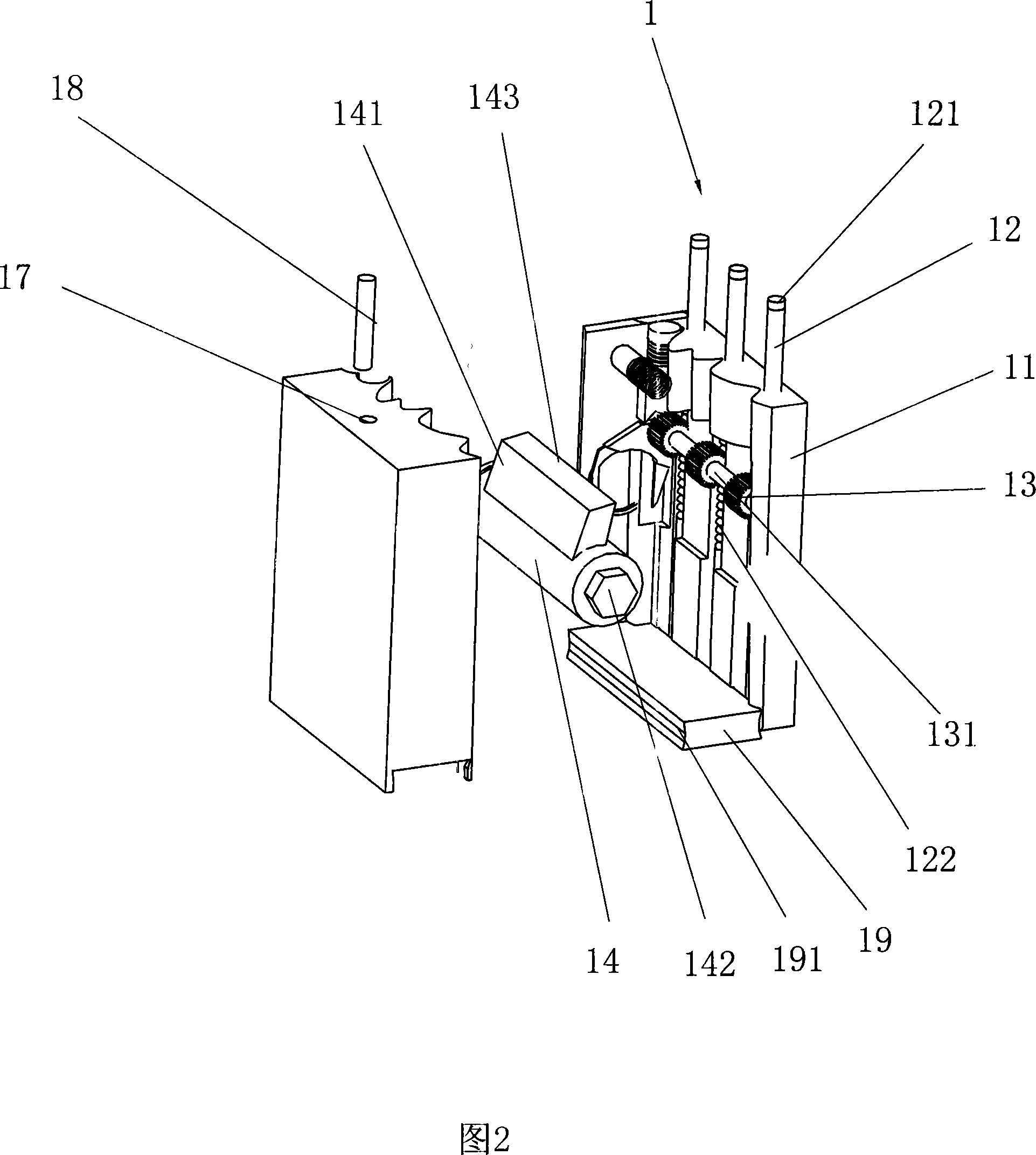
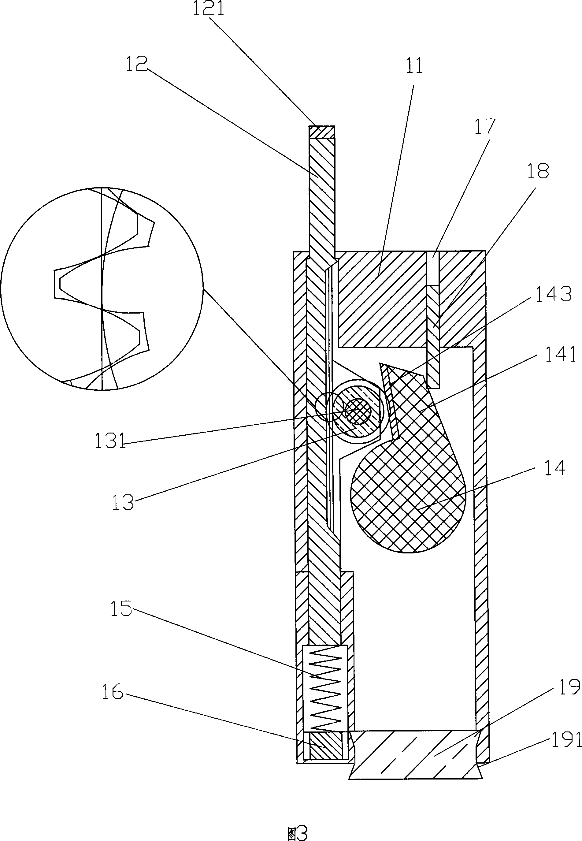
[0021] 11. Main frame; 12. Ejector with rack; 121. Soft layer; 122. Rack; 13. Gear; 131. Gear shaft; 14. Connecting shaft; 141. Brake block; 142. Protrusion; 143, rubber layer; 144, blind hole; 15, elastic member, 16, spring adjustment screw; 17, hole; 18, brake block locking column; 19, base connection block; 191, dovetail groove.

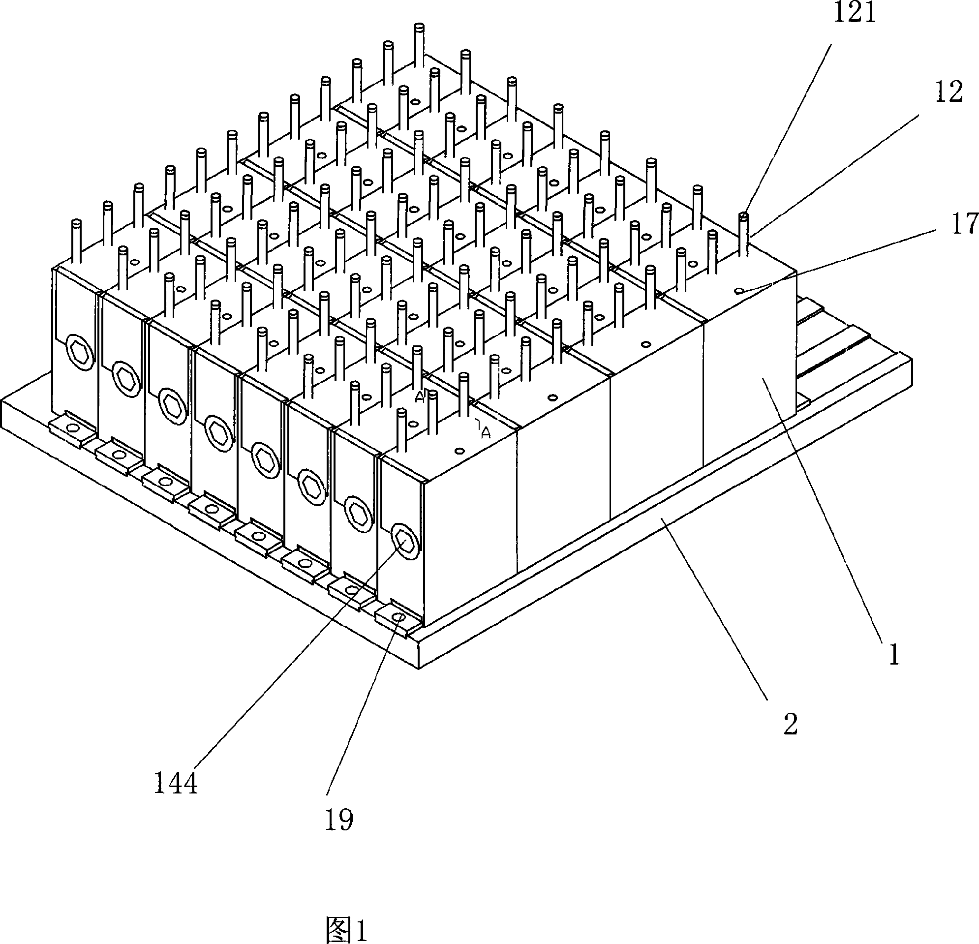
[0022] Please refer to Fig. 1, it is a passive combined multi-purpose thimble device, it has 32 thimble units 1 arranged on the base 2 of a whole board, and the thimble units 1 are detachably arranged on the base through the base connecting block 19 on the base 2.

[0023] Apparently, the aforementioned bases 2 can also be strip-shaped, and one or more thimble units 1 can be arranged on each base 2 , and two or more strip-shaped bases 2 can be assembled into an integral structure.

[0024] Please refer to Figure 2 and Figure 3, Figure 2 is a schematic cross-sectional view of the thimble unit in Figure 1;...


PUM


Abstract

A non-active assembled multifunctional thimble device is realized by arranging 32 thimble units on a base (2) which is an integrated board. The thimble units are detachably arrayed on the base (2) by a base connecting block (19). The base (2) can be in the shape of strips, one or more thimble units is/are arranged on each strip-shaped base (2), and two or more strip-shaped bases (2) are jointed to form an overall structure. The invention adopts a mode of assembling a plurality of thimble units on a base, which can satisfy supporting requirements for printed circuit boards in different sizes to realize general propose. With the combination of rack rod and gear, structure of braking block, and arrangement of spring below the rack rod, requirement for elements with different sizes can be satisfied. By adopting such a structure that one end of a connecting shaft is a ridge-shaped protrusion and the other end is a blind hole with shape and size joggled with the ridge-shaped protrusion, series connection of two adjacent thimble units can be easily realized.

Description

technical field [0001] The invention relates to a thimble device used on a printing machine or a placement machine, in particular to a passive combined multipurpose thimble device. Background technique [0002] In the field of surface mount technology (SMT), in the working process of printing machines or placement machines, in order to ensure the quality of placement, the main thimble device is used to support the printed circuit board. The basic structure of the thimble device is many thimbles distributed on the base. The ejector pins hold against the printed circuit board. According to the structure of the thimble and the power source used, the existing thimble devices can be divided into three categories: hard thimbles, gas thimbles or soft thimbles. These three types of thimble devices have their own advantages and disadvantages, and their application ranges are also different, but they have a common disadvantage, that is, they cannot meet the requirements of various pr...

Claims


Application Information

Patent Timeline
Patent Type & Authority Applications(China)
IPC IPC(8): H05K13/04
Inventor 杨建华
Owner 杨建华
Why Eureka
Try Eureka