Rotating stripping head for cable stripping apparatus

A technology for stripping equipment and cables, which is applied in the field of rotary insulator stripping heads, can solve problems such as complex manufacturing processes, and achieve the effects of low production cost, easy production, and easy cost

Active Publication Date: 2008-03-19
SCHLEUNIGER HLDG AG A CO INC UNDER THE LAWS OF SWITZERLAND
View PDF3 Cites 15 Cited by
  • Summary
  • Abstract
  • Description
  • Claims
  • Application Information

AI Technical Summary

Problems solved by technology

This device requires a fairly complex manufacturing process, especially if the equipment has the desired precision

Method used


Image

  • Rotating stripping head for cable stripping apparatus
  • Rotating stripping head for cable stripping apparatus
  • Rotating stripping head for cable stripping apparatus

Examples


Embodiment Construction

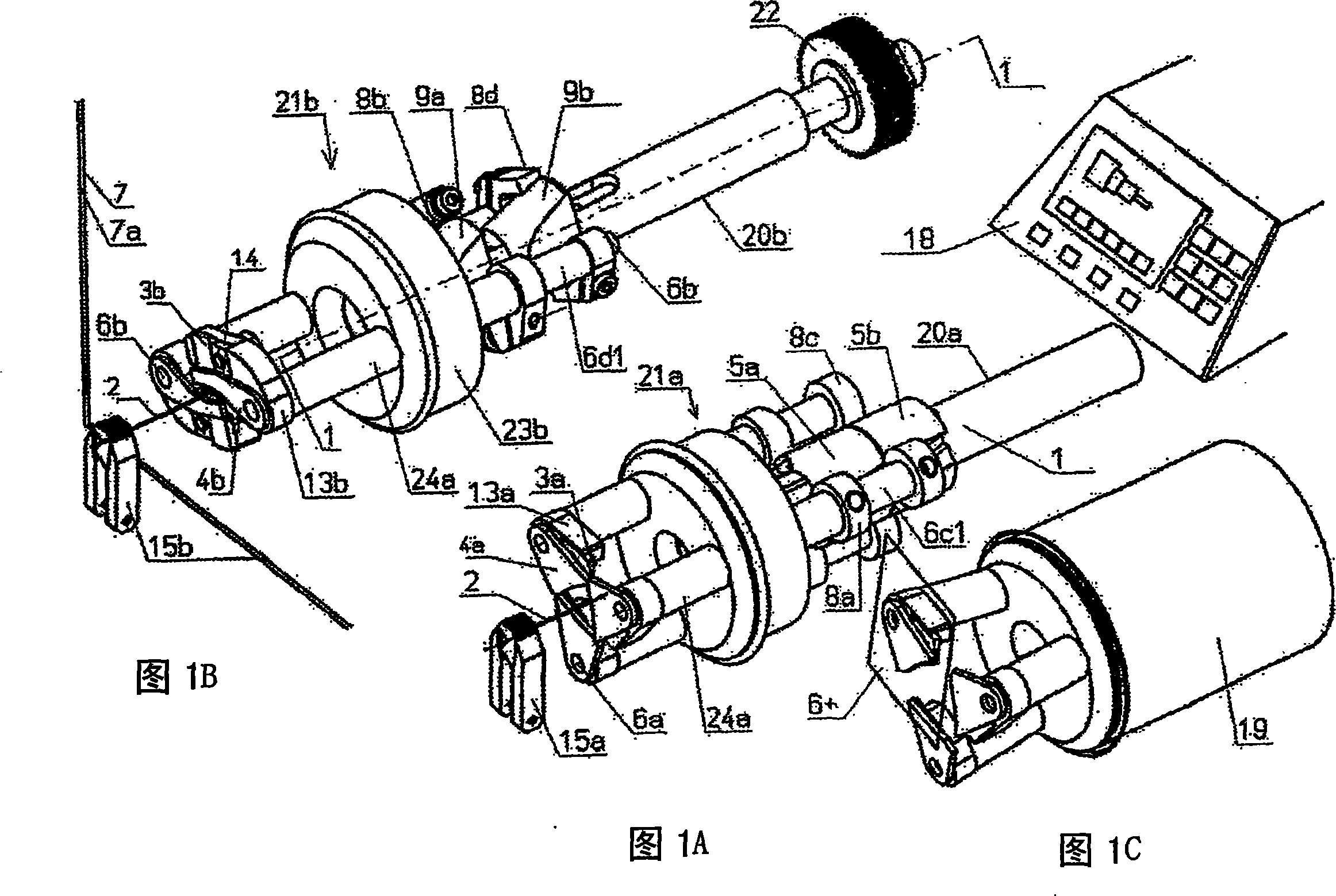
[0058] For a certain function, the different insulation stripping heads according to FIGS. 1 a and 1 b should be considered together.

[0059] For simplicity, they are both shown with their insulation stripping blades 3a, 3b in the normal plane 7 of the main axis 1 (common in the figure). According to an embodiment, the clamping device 15 is displaceable relative to this normal plane 7, so that, as shown in FIG. 7 is pushed into the space behind the insulation stripping blade 3a, and at the same time, in the diagram according to FIG. Pull out from the space behind the insulation stripping blade 3b and back before the normal plane 7, and pieces (not visible in the figure) have been removed. The fragments fall into the space behind the insulation stripping blade 3b, or remain on the conductors of the cable 2 etc. as long as a limited insulation stripping (with a "window") is set.

[0060]Especially in the case of those insulation stripping plants in which the clamping device i...


PUM


Abstract

The invention relates to a novel insulation stripping head which can also be used in particular as a spare part for existing rotational insulation stripping apparatuses. It is particularly stable and simple to produce while at the same time providing the same or improved precision. It substantially has insulation stripping blades (3) and centering jaws (4) which can be swiveled in laterally and, during operation for insulation stripping, rotate together about the main axis (1).

Description

technical field [0001] The invention relates to a rotary insulation stripping head for an insulation stripping plant for conductors which can be arranged along a main axis, in particular with multiple layers of insulation (coaxial cables) , optical fiber, insulated wire, etc. In particular, however, the invention relates without limitation to a continuous cable that is not fed in a continuous method (i.e., where there is no feed entering on one side of the machine and exiting on the other side of the machine, but instead, Insulation stripping equipment that operates by feeding cables that are introduced into the machine on one side and removed from the machine in the opposite direction. Background technique [0002] Many such insulation stripping devices are known in the prior art. The most famous and common worldwide devices for coaxial cables were invented by the applicant and are designated under the names of the following types: HC207, MP257, MP8015, MC252, CS5300, CS5...

Claims


Application Information

Patent Timeline
Patent Type & Authority Applications(China)
IPC IPC(8): H02G1/12G02B6/24
CPCG02B6/4497H02G1/1265G02B6/245G02B6/566
Inventor 伊里·斯特潘托马斯·斯特潘
Owner SCHLEUNIGER HLDG AG A CO INC UNDER THE LAWS OF SWITZERLAND
Why Eureka
Try Eureka