Differential capacitance type sensor detection circuit

A technology of differential capacitance and detection circuit, which is applied in the direction of electronic circuit testing, circuit, and transmission of sensing components by electric/magnetic devices, etc., can solve the problem of low detection accuracy and achieve high detection accuracy, high reliability, and reasonable structure Effect

Inactive Publication Date: 2008-03-26
ZHONGBEI UNIV
View PDF0 Cites 26 Cited by
  • Summary
  • Abstract
  • Description
  • Claims
  • Application Information

AI Technical Summary

Problems solved by technology

[0003] In order to solve the problem that the detection accuracy of the modulation and demodulation detection circuit adopted by the

Method used


Image

  • Differential capacitance type sensor detection circuit
  • Differential capacitance type sensor detection circuit
  • Differential capacitance type sensor detection circuit

Examples


Embodiment Construction

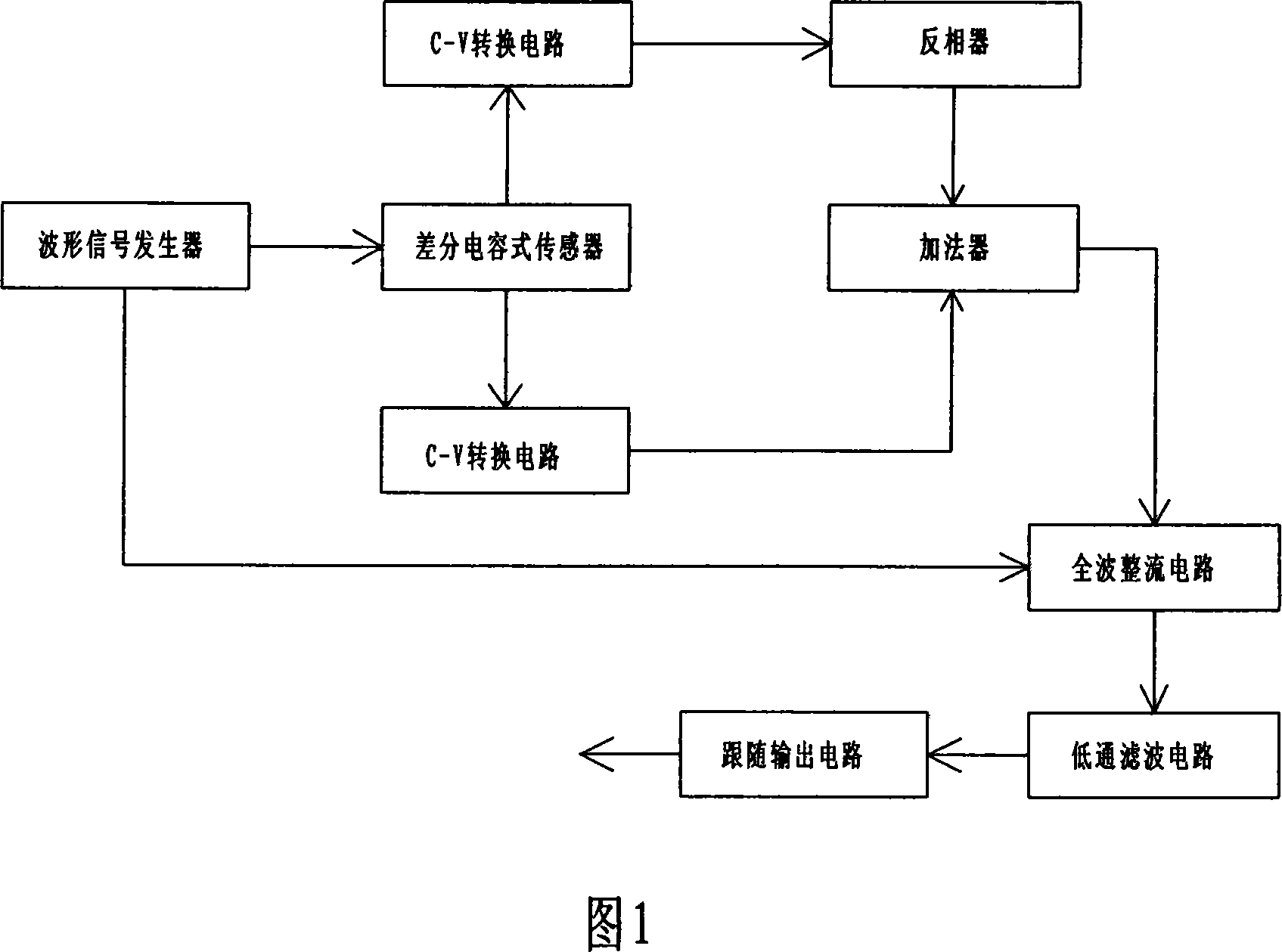
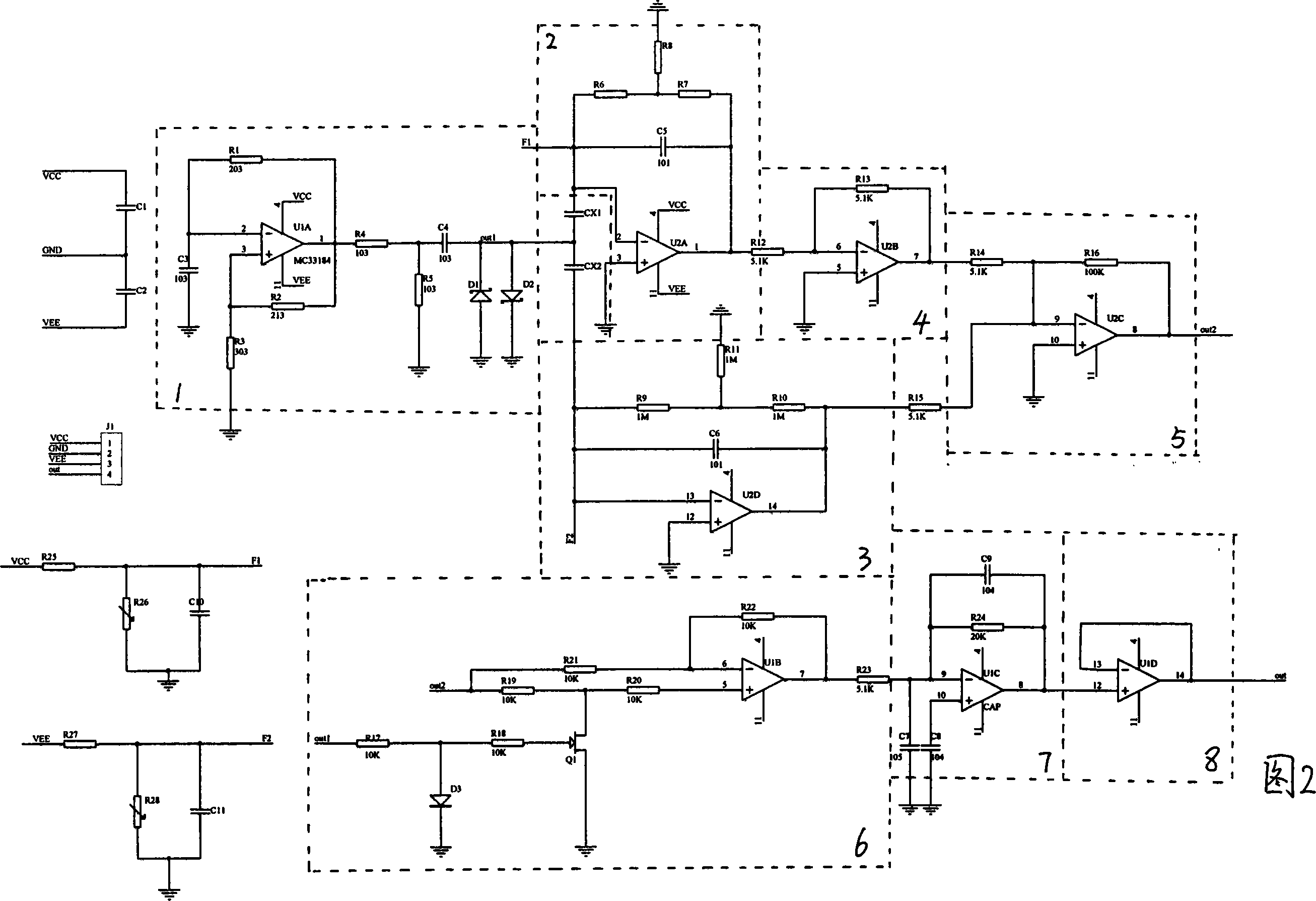
[0019] The differential capacitive sensor detection circuit includes a waveform signal generator 1, C-V conversion circuits 2 and 3, an inverter 4, an adder 5, a full-wave rectification circuit 6, a low-pass filter circuit 7, and a follower output circuit 8. The wave rectification circuit includes an integrated operational amplifier U1B and a transistor Q1. The inverting terminal of the integrated operational amplifier U1B is connected to the output terminal out2 of the adder through a resistor R21, and the non-inverting terminal is connected to the output terminal out2 of the adder through resistors R19 and R20. Resistor R22 is connected between the terminal and its output terminal, the connection node of resistors R19 and R20 is connected to the collector of transistor Q1, the base of transistor Q1 is connected to the output terminal out1 of the waveform signal generator through resistors R17 and R18, resistors R17, The connection node of R18 is grounded via diode D3. The C-...


PUM


Abstract

This invention relates to weak signal test technology, specifically it is a kind of difference capacitance sensor test circuit. It solves the problem that the test precision of the exist difference capacitance sensor test circuit is not high, includes the full wave rectifying circuit, the said full wave rectifying circuit includes the integrated amplification circuit U1B and dynatron Q1, the phase reversal end of the integrated amplification U1B links with the output end out2 of the summator by the resistance R21, the in-phase end links with the output end out2 of the summator by the resistance R19,R20, the resistance R22 is set between the phase reversal end and the output end, the connection node of the resistance R19,R20 connects the collector electrode of the dynatron Q1, the base electrode of the dynatron Q1 links with the output end out1 of the waveform generator by the resistance R17, R18, the connection node of the resistance R17, R18 earth by the diode D3. The structure of the invention is in reason, the test precision of the weak signal produced by the difference capacitance sensor, the reliability is high.

Description

technical field [0001] The invention relates to weak signal detection technology, in particular to a differential capacitive sensor detection circuit. Background technique [0002] At present, there are many methods and circuits to realize the detection circuit of MEMS device-differential capacitive sensor: 1. The method of converting capacitance signal into frequency signal; 2. Phase measurement method; 3. Using switched capacitor circuit; 4. Using modulation and demodulation Type circuits, etc. Among them, in modulation and demodulation circuits, the circuits that are often used are as follows: a waveform signal generator whose output end is connected to the movable plate of the differential capacitive sensor, and an input end connected to two fixed plates of the differential capacitive sensor Two C-V conversion circuits connected to the electrodes, an adder, a full-wave rectification circuit connected to the output end of the adder, a low-pass filter circuit connected to ...

Claims


Application Information

Patent Timeline
IPC IPC(8): G01P15/125G01P21/00G01P21/02G01R31/28H03K17/60G01D5/24
Inventor 刘俊石云波崔永俊杨玉华马宗敏王玲
Owner ZHONGBEI UNIV
Why Eureka
Try Eureka