
Base plate impedance match device

A technology of impedance matching and substrate, applied in the direction of electrical components, electric solid devices, circuits, etc., can solve the problems of reduced flexible space of the substrate, increased cost, and inability to effectively reduce the wiring flexibility and elasticity of the wiring area.

Active Publication Date: 2008-03-26
ADVANCED SEMICON ENG INC
View PDF0 Cites 3 Cited by
  • Summary
  • Abstract
  • Description
  • Claims
  • Application Information

AI Technical Summary

Problems solved by technology

However, its disadvantages are the increase in cost, the reduction of the flexible space of the substrate, and the inability to effectively reduce the wiring area required for the matching network in the package structure and increase the flexibility and flexibility of wiring.

Method used


Image

  • Base plate impedance match device
  • Base plate impedance match device
  • Base plate impedance match device

Examples


Embodiment Construction

[0014] Relevant detailed description and technical contents of the present invention are as follows now in conjunction with the accompanying drawings:

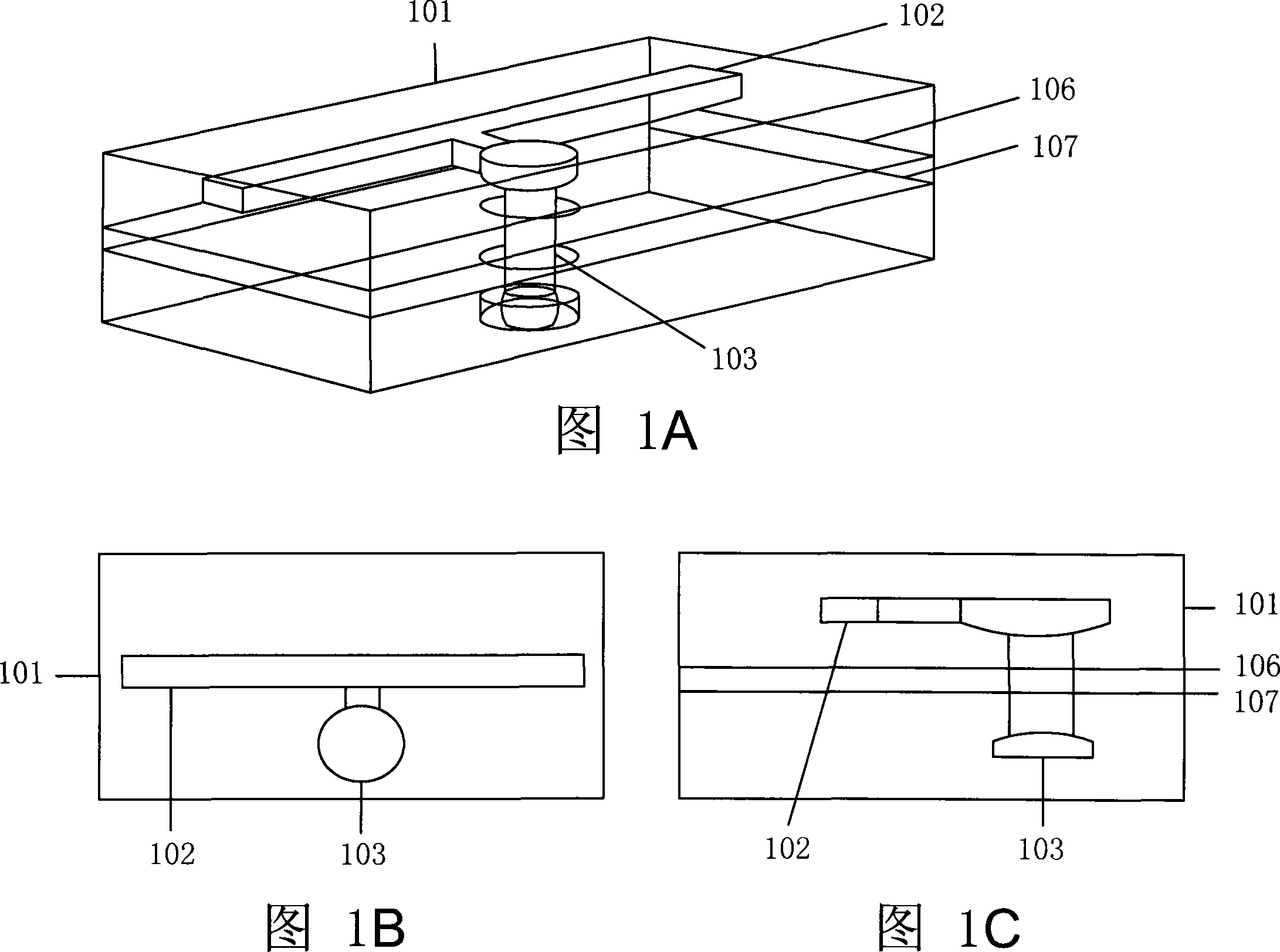
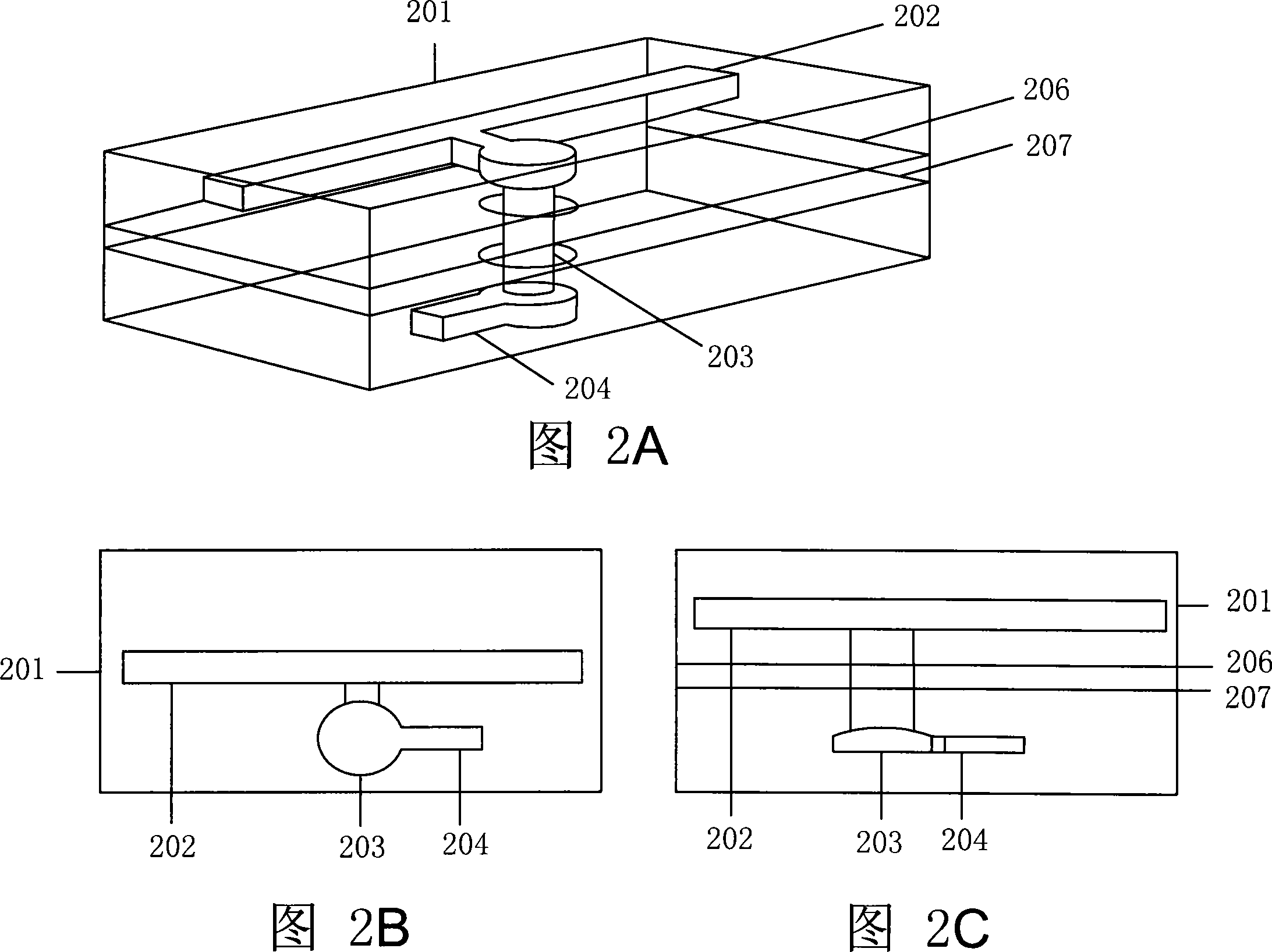
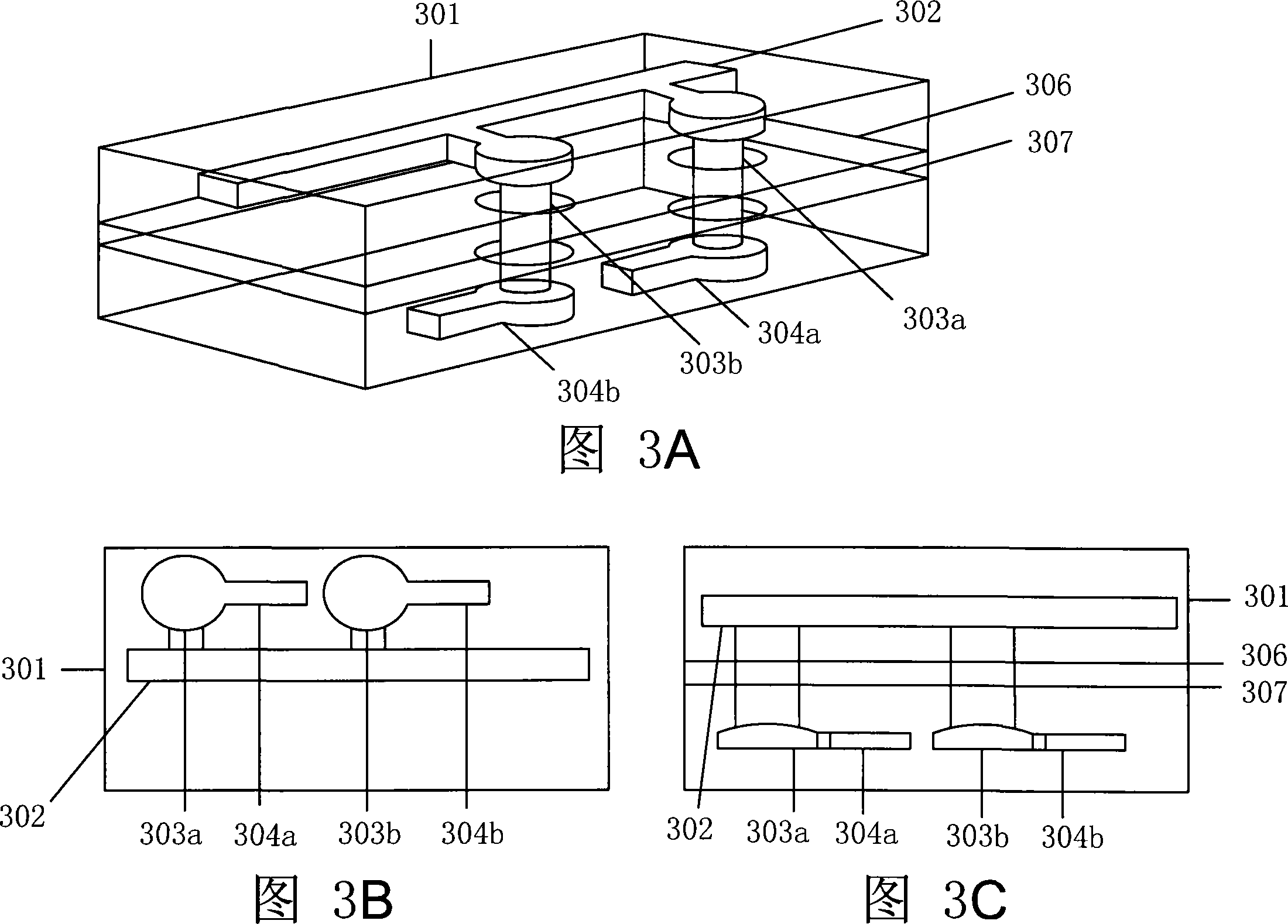
[0015] 1A to 1C are structural schematic diagrams of the first embodiment of the present invention. As shown in FIG. 1A , the substrates 106 and 107 can form a package 101 in a stacked form through the existing lamination technology used in the System in Package (SiP) process, wherein the package 101 is used as a complete The part used for impedance matching in the package structure, since the features of the present invention have nothing to do with the package structure, the relevant illustrations and descriptions are omitted for the sake of simplicity and clarity, and this embodiment only describes the impedance matching part in detail . As shown in FIG. 1A, the package body 101 has a metal circuit 102 arranged in parallel above the substrates 106, 107. The metal circuit 102 is used to transmit electrical signals in the ho...


PUM


Abstract

This invention relates to a device for realizing match of impedance to base boards suitable for the current system package structure and high density I / O system package design, which realizes impedance match among different systems by conducting lines vertical and connected to the metal circuits on the surface of the board or connects transmission lines of incomplete segment horizontal to the metal circuits at the end of the vertical conducting lines to realize match of impedance among different systems.

Description

technical field [0001] The present invention relates to a substrate impedance matching device, in particular to an impedance matching device that uses only a vertical conducting line or uses a vertical conducting line with a stub transmission line to realize impedance matching between different systems in the form of stub transmission . Background technique [0002] In the current electronics industry, the system package structure (System in Package) gradually tends to be light, thin, short, small and multi-functional along with electronic products such as mobile phones, Bluetooth systems, personal digital assistants and digital cameras. The number of electronic components and circuit pins in these electronic products is also gradually increasing, and they are becoming smaller and smaller. Therefore, integrating subsystems such as microprocessors and memory units into one chip can achieve the most delicate system packaging technology has become an important trend in the fut...

Claims


Application Information

Patent Timeline
IPC IPC(8): H01L23/488H01L23/66
CPCH01L2924/0002
Inventor 庄宗颖李宝男
Owner ADVANCED SEMICON ENG INC
Learn More