Defibrillator with impedance-compensated energy delivery

A defibrillator and energy source technology, applied in the field of defibrillators, can solve the problems of expensive implantable defibrillators

Inactive Publication Date: 2008-03-26
KONINKLIJKE PHILIPS ELECTRONICS NV
View PDF10 Cites 1 Cited by
  • Summary
  • Abstract
  • Description
  • Claims
  • Application Information

AI Technical Summary

Problems solved by technology

However, implantable defibrillators are expensive and are used in only a fraction of all people at risk of sudden cardiac death

Method used


Image

  • Defibrillator with impedance-compensated energy delivery
  • Defibrillator with impedance-compensated energy delivery
  • Defibrillator with impedance-compensated energy delivery

Examples


Embodiment Construction

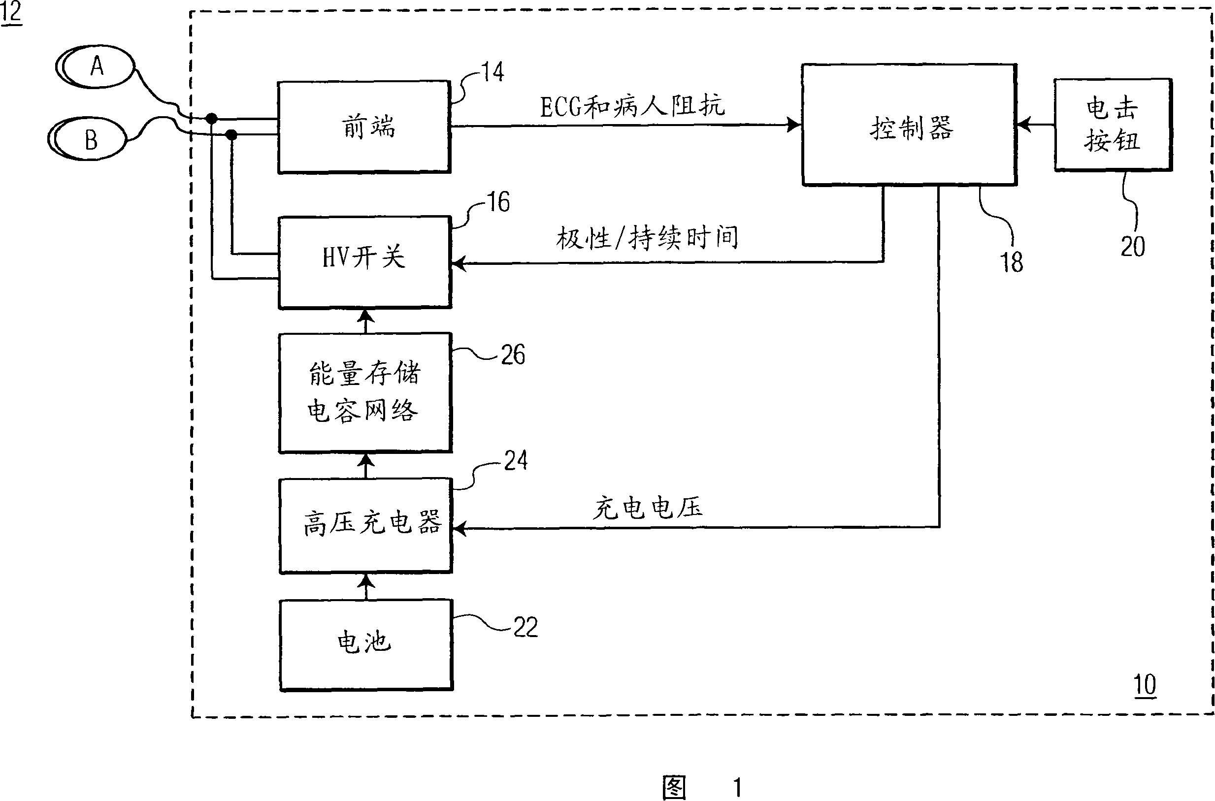
[0019] Referring first to FIG. 1 , a simplified block diagram of a defibrillator 10 in accordance with the present invention is shown. A pair of electrodes 12A and 12B for connection to a patient (not shown) are connected to the front end 14 and further connected to a high voltage (HV) switch 16 . The front end 13 is used to detect, filter and digitize the ECG signal and patient impedance from the patient. The ECG signal is then provided to a controller 18 which runs a shock advisory algorithm capable of detecting ventricular fibrillation (VF) or other shock rhythms resulting from electrotherapy therapy.

[0020]Front end 14 is capable of measuring patient impedance between electrodes 12 by any of several techniques described below. One technique utilizes and measures the patient's response to a low potential test signal. With this technique, a low potential non-therapeutic electrical signal is delivered to the patient prior to delivery of a defibrillation pulse, and the vol...


PUM


Abstract

An external defibrillator is described which maintains the durations of phases of a multiphasic shock waveform within or below desired limits. As the duration of a waveform increases for patients of increased patient impedance, the durations of the phases of a multiphasic shock waveform also increase. Before a maximum duration limit is exceeded, the defibrillator adds another phase to the multiphasic waveform which brings the durations of the phases within the desired range or below a maximum duration limit. Both the number of shock phases and the individual phase durations can be controlled in response to measured patient impedance.

Description

technical field [0001] The present invention relates to electrotherapy devices and methods, and more particularly to defibrillators for delivering defibrillation pulses to a patient in an impedance-compensated manner. Background technique [0002] Sudden cardiac death is the leading cause of death in the United States. Most sudden cardiac deaths are caused by ventricular fibrillation, in which the heart's muscle fibers contract uncoordinatedly, preventing the normal flow of blood to the body. Electrochemical reactions in the human heart normally cause the heart's muscle fibers to contract and relax in a synchronized fashion, effectively pumping blood from the ventricles to the body's vital organs. Sudden cardiac death is usually caused by ventricular fibrillation (VF), in which an abnormal electrical response in the heart causes individual muscle fibers to contract in an asynchronous and chaotic manner. The only effective treatment for VF is electrical defibrillation, in w...

Claims


Application Information

Patent Timeline
Patent Type & Authority Applications(China)
IPC IPC(8): A61N1/39
CPCA61N1/3937A61N1/3906
Inventor D·斯奈德
Owner KONINKLIJKE PHILIPS ELECTRONICS NV
Why Eureka
Try Eureka