Illuminating system based on light emitting diode and its driving circuit and method

A technology of light-emitting diodes and driving circuits, applied in electroluminescent light sources, light sources, electric light sources, etc., can solve the problem that LED brightness cannot be freely adjusted, and achieve good dimming effect.

Inactive Publication Date: 2008-04-02
MAISHI ELECTRONICS (SHANGHAI) LTD
View PDF1 Cites 22 Cited by
  • Summary
  • Abstract
  • Description
  • Claims
  • Application Information

AI Technical Summary

Problems solved by technology

The prior art mentioned above cannot real

Method used


Image

  • Illuminating system based on light emitting diode and its driving circuit and method
  • Illuminating system based on light emitting diode and its driving circuit and method
  • Illuminating system based on light emitting diode and its driving circuit and method

Examples


Example Embodiment

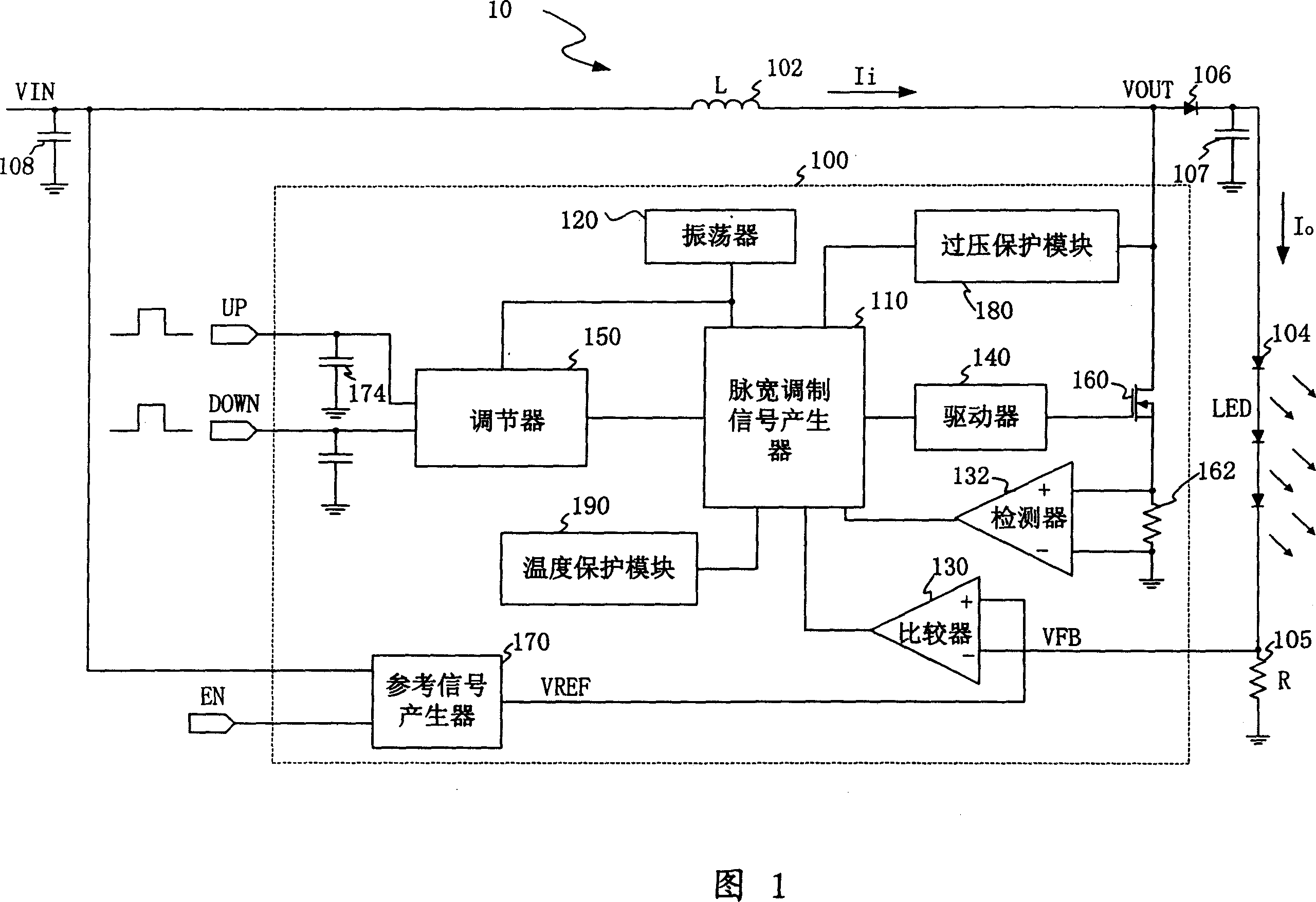
[0018] FIG. 1 is a circuit block diagram of a light emitting system 10 including a light emitting diode driving circuit 100 of the present invention. The light emitting system 10 includes a driving circuit 100, an energy storage element 102 and a number of light emitting diodes (LEDs) 104 connected in series. In this embodiment, the energy storage element 102 is an inductor.

[0019] The LED driving circuit 100 of the present invention includes a pulse width modulation signal (PWM) generator 110, an oscillator 120, a comparator 130, a driver 140, a regulator 150 for adjusting the brightness of the LED 104, and a switch 160. The non-inverting input terminal of the comparator 130 receives a reference signal, such as a voltage reference signal VREF representing the expected brightness of the LED, and its inverting input terminal receives a voltage feedback signal that is detected by the feedback resistor 105 and is proportional to the actual current flowing through the LED VFB, where...


PUM


Abstract

A luminous system based on a luminous diode and a luminous diode driver circuit and method are disclosed in the present invention. The driver circuit comprises a switch, a pulsewidth modulation signal generator and a regulator coupling with the pulsewidth modulation signal generator. To control the conducting time and the closing time of the switch according to the duty-ratio of the pulsewidth modulation signal generated by the pulsewidth modulation signal generator, so as to regulate the current provided to the luminous diode. One input end of the regulator receives the external input signal, and outputs a controlling signal to the pulsewidth modulation signal generator according to the external input signal, regulates the duty-ratio of the pulsewidth modulation signal generated by it, leads the luminous diode current to be able to increase or decrease according to the external input signal, thereby realizes to regulate the brightness of the luminous diode freely.

Description

technical field [0001] The invention relates to a lighting system, a driving circuit and a driving method, in particular to a lighting system based on a light emitting diode, a driving circuit and a driving method of the light emitting diode. Background technique [0002] Due to many advantages such as low power consumption, long life, and compact structure, light-emitting diodes (LEDs) are widely used in liquid crystal displays (LCDs) of personal digital assistants (PDAs), mobile phones (Mobile Phones) and other devices as background light sources. . The LED is driven by a DC / DC converter, which converts the input voltage provided by the power supply into the output voltage required by the LED by controlling the on and off of the switch. Usually, pulse width modulation (PWM) technology is used to adjust the current of the LED to control the change of the LED current. The current of the LED is modulated by a PWM control signal in the feedback loop. [0003] US Patent Publ...

Claims


Application Information

Patent Timeline
IPC IPC(8): H05B33/08H05B44/00
Inventor 杨申
Owner MAISHI ELECTRONICS (SHANGHAI) LTD
Why Eureka
Try Eureka