Diffuse transmission measuring and correcting method of cone-beam CT system

A correction method, cone beam technology, applied in the direction of radiation intensity measurement, instruments for radiological diagnosis, material analysis using radiation, etc., can solve problems such as ineffective application

Inactive Publication Date: 2008-04-09
NORTHWESTERN POLYTECHNICAL UNIV
View PDF0 Cites 42 Cited by
  • Summary
  • Abstract
  • Description
  • Claims
  • Application Information

AI Technical Summary

Problems solved by technology

[0007] In order to overcome the deficiency that the existing technology cannot be effectively applied to industrial nondestructive testing, the present invention provides a set of scatter measurement scheme and correction algorithm of cone beam CT system to solve the scatter correction of medium and high energy cone beam CT system in industrial application problems, so as to obtain high-quality and high-precision reconstructed slice images

Method used


Image

  • Diffuse transmission measuring and correcting method of cone-beam CT system
  • Diffuse transmission measuring and correcting method of cone-beam CT system
  • Diffuse transmission measuring and correcting method of cone-beam CT system

Examples


Embodiment Construction

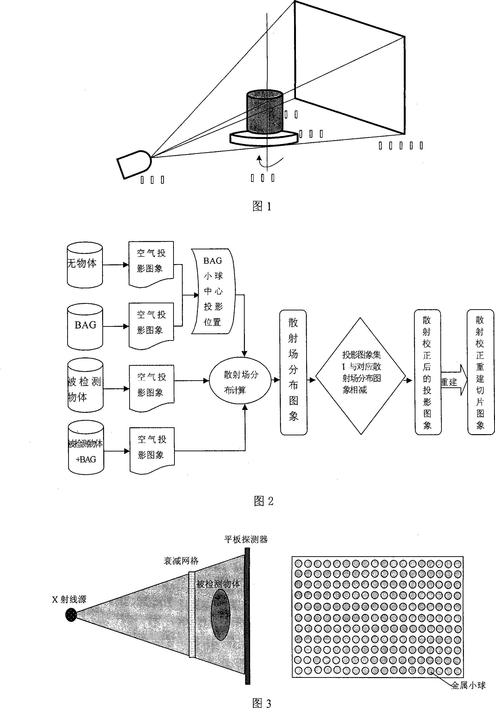
[0044] Cone-beam CT scanning is carried out on a cylindrical detection part with a diameter of 40mm and the material is aluminum. The X-ray source adopts German YXLON Y.TU 450-D02, and the flat panel detector adopts American Varian PaxScan2520, and the method of the present invention is used for scattering correction , as shown in Figure 2, perform the following steps:

[0045] 1. According to the object to be detected, the projection magnification ratio of the cone beam CT scan is 1.18, the full resolution acquisition speed of the flat panel detector is 3 frames per second, the scanning voltage is 280KV, and the scanning current is 0.25mA. These parameters are related to the projection image below The steps of data acquisition remain unchanged;

[0046] 2. Without placing any objects, collect 6 air projection images through the flat panel detector, and take the average value as the air projection image to be used;

[0047] 3. Place the beam attenuation grid between the X-ray...


PUM


Abstract

The invention discloses a scattering determination and corrector method of a taper bunch CT system. After arranging a parameter, an air projected picture and a beam attenuation grid projected picture are collected. A circular scanning is carried out on the detected object. A projected picture set I of the detected object with beam attenuation grid and a projected picture set II of the detected object are collected. The projected attitude of the center of each metal ball in the beam attenuation grid is calculated. A scattered field distributing image corresponding to the projected picture of the projected picture set I is calculated through a beam attenuation grid corrector method. A projected picture set III after scattering correction is gained through the projected picture set I subtracting the corresponding scattered field distributing image. Thereby, a sequence slice image after scattering correction is reconstructed through a filter back-projection reconstruction method. The invention can be applied to the scattering correction of the taper bunch CT system from low energy to medium or high energy. The invention is a simple and effective scattering correction method of the taper bunch CT system.

Description

technical field [0001] The invention belongs to the field of non-destructive testing, and relates to a scattering measurement and correction method of a cone-beam CT system. Background technique [0002] Cone Beam Computed Tomography (CBCT), a high-resolution cone beam CT (Cone Beam Computed Tomography, CBCT), generates cone beam rays from an X-ray source, and uses an area array detector to collect projection images of the object to be inspected. a high-tech. Compared with traditional two-dimensional CT, CBCT has a very high scanning speed. In one scanning cycle, it can scan a large number of tomographic images, obtain XYZ three-way high-precision spatial resolution images, and reconstruct slice images It has the characteristics of continuous slice sequence, same spatial resolution within and between slices, and high precision. [0003] At present, the technical bottleneck restricting the wide application of cone-beam CT system is the image quality of reconstructed slices,...

Claims


Application Information

Patent Timeline
Patent Type & Authority Applications(China)
IPC IPC(8): G01N23/04G01T1/16
CPCA61B6/5282
Inventor 张定华黄魁东卜昆胡栋材
Owner NORTHWESTERN POLYTECHNICAL UNIV
Why Eureka
Try Eureka