Engine crankshaft dynamic analysis method

A technology of dynamic analysis and analysis method, which is applied in the field of engine crankshaft dynamic analysis, and can solve problems such as lengthening the development cycle and increasing costs

Active Publication Date: 2008-04-09
CHERY AUTOMOBILE CO LTD
View PDF1 Cites 26 Cited by
  • Summary
  • Abstract
  • Description
  • Claims
  • Application Information

AI Technical Summary

Problems solved by technology

If changes are made after production, it will not only lengthen the development cycle but also increase the cost of development

Method used


Image

  • Engine crankshaft dynamic analysis method
  • Engine crankshaft dynamic analysis method
  • Engine crankshaft dynamic analysis method

Examples


Embodiment Construction

[0021] The analysis method of the present application will be further described in conjunction with the accompanying drawings.

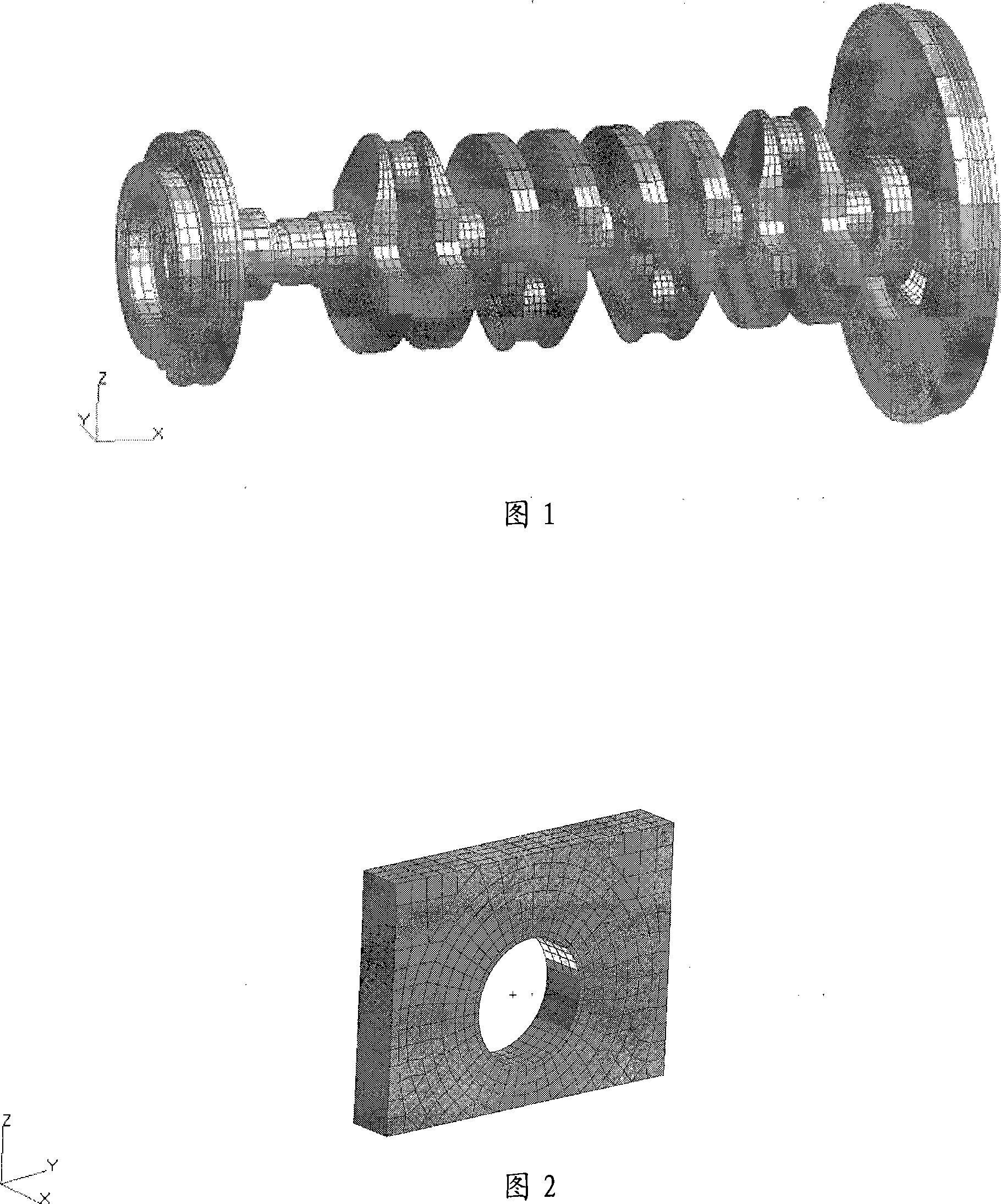
[0022] 1. Mesh division:

[0023] 1.1 Mesh division of crankshaft system

[0024] When meshing the crankshaft system, in order to ensure the smooth progress of the dynamic analysis of the crankshaft system and high calculation accuracy, it is necessary to ensure sufficient mesh accuracy at the fillet, as shown in Figure 1. Due to the large model of the crankshaft system and many calculation conditions, the calculation of the crankshaft system adopts the substructure analysis method, that is, the modal compression method.

[0025] 1.2 Simple main bearing wall finite element model

[0026] The simple main bearing wall FE model adopts hexahedral mesh, and the number of unit layers in the main bearing wall hole is required to be the same as that on the crankshaft main journal, which must be equally divided and equally spaced. as shown in picture 2.

...


PUM


Abstract

The invention discloses an analysis method of motor crank dynamics, which includes that: in Hypermesh software, a crank system is divided by finite element mesh generation into a crank, a flywheel, a belt pulley, a timing gear and a main bearing seat etc.; use Nastran software to execute the reduction solving of a finite element substructure; in EXCITE software, construct a model of the crank system dynamics, and exert the corresponding boundary condition on elements to implement simulation calculation; use the Nastran software to implement restoration solving of dynamic stress on the crank, perform post-processing and execute fatigue analysis on dangerous points; reasonably evaluate the crank system according to the results, and if the structure is not reasonable, the structure optimization is still needed. The method uses EXCITE calculation technique to execute dynamics analysis on the motor crank, obtains the strength and the fatigue parameters of the motor crank, and further evaluates the structure parameters of the crank and the related parts of the motor reasonably, therefore, making the improvement thereof.

Description

technical field [0001] The present invention relates to engine crankshaft dynamics analysis. Background technique [0002] It is very important to predict the strength and fatigue of engine crankshaft dynamics in the stage of engine concept design. In the conceptual design stage, many parameters are in an undetermined state, and these parameters need to be changed according to the requirements such as engine crankshaft dynamics. Engine crankshaft strength and fatigue are a major consideration. There are so many influencing factors that it is difficult to obtain specific influencing factors. If changes are made after production, it will not only lengthen the development cycle but also increase the cost of development. Contents of the invention [0003] The invention discloses a dynamic analysis method for an engine crankshaft, specifically as follows: [0004] Carry out finite element mesh division of crankshaft system in Hypermesh software: crankshaft, flywheel, pulley...

Claims


Application Information

Patent Timeline
Patent Type & Authority Applications(China)
IPC IPC(8): G06F17/50
Inventor 骆富贵
Owner CHERY AUTOMOBILE CO LTD
Why Eureka
Try Eureka