Synchronous control method and circuit of electromagnetic stove

A synchronous control, induction cooker technology, applied in induction heating control, induction heating and other directions, can solve the problems of hardware synchronous circuit deviating from the resonant frequency of LC oscillation circuit, easily damaged switch tube IGBT, complicated circuit debugging, etc., to achieve stable working frequency and debugging. Convenient, simple circuit effect

Inactive Publication Date: 2008-04-09
SHENZHEN H&T INTELLIGENT CONTROL
View PDF0 Cites 30 Cited by
  • Summary
  • Abstract
  • Description
  • Claims
  • Application Information

AI Technical Summary

Problems solved by technology

[0005] The main disadvantages of the existing technology are: using hardware circuits to realize synchronous control, the circuit is complicated and the cost is high; the circuit debugging is complicated, and the switch tube IGBT is easy to be damaged; long-term use makes the hardware synchronous circuit deviate from the resonant frequency of the LC oscillation circuit

Method used


Image

  • Synchronous control method and circuit of electromagnetic stove
  • Synchronous control method and circuit of electromagnetic stove

Examples


Embodiment Construction

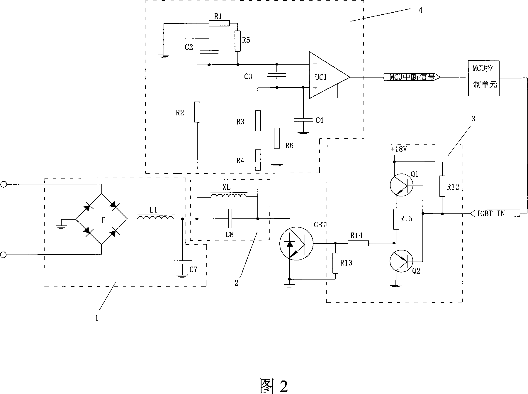
[0021] A synchronous control circuit for an induction cooker as shown in FIG. 2 includes a rectification filter circuit 1, a resonant circuit 2, a drive circuit 3, a synchronous signal circuit 4, an MCU control module and a switching device IGBT tube.

[0022] The rectifying and filtering circuit 1 includes a rectifying bridge stack F, an inductor L1 and a capacitor C7. The resonant circuit 2 includes a capacitor C8 and a reel inductance XL. The driving circuit 3 includes a transistor Q1, a transistor Q2, a resistor R12, a resistor R13 and a resistor R14. The synchronization circuit 4 includes a comparator UC1 , a capacitor C2 , a capacitor C3 , a capacitor C4 , a resistor R1 , a resistor R2 , a resistor R3 , a resistor R4 , a resistor R5 and a resistor R6 .

[0023] The working process of the above circuit is: the MCU controls the control unit to output an IGBT IN signal, which is a high-level signal with a set width. After the drive circuit 3 receives the signal, it drives ...


PUM


Abstract

The invention discloses a synchronization control method for an electromagnetic oven and a circuit thereof. The circuit includes a rectification filter circuit, a resonance circuit, a switch device, a drive circuit, a synchronizing signal circuit and a MCU control unit. The synchronization control method is: a synchronizing signal circuit detects the resonance voltage of a resonance circuit; when the resonance voltage decreases to a set value, the synchronizing signal circuit generates a synchronizing interrupt pulse signal; the MCU control unit detects the synchronizing interrupt pulse signal and outputs a high level continuity signal with specific width to a drive circuit, which controls the conduction of the switch device; after the high level continuity signal finishes, the switch device intercepts and the resonance circuit generates a resonance; and repeats the process. The invention adopts the MCU control unit to output the high level continuity signal to the drive circuit, in order to directly control the conduction and interception of the switch device, exerts the advantage of MCU stable working frequency and improves the synchronization course precision, with the advantages of simple circuit, convenient debugging and low cost.

Description

technical field [0001] The invention relates to a synchronous control method and a circuit, in particular to a synchronous control method and a circuit of an electromagnetic oven. Background technique [0002] The general circuit principle of the induction cooker is as follows: the mains power is converted into DC power by a bridge rectifier filter circuit, and then converted into high-frequency AC power by a voltage resonant converter. The voltage resonant converter is generally a power switching tube, such as an IGBT tube, which is turned on and off by a controller through a drive circuit. The synchronous control unit is one of the key circuit units in the induction cooker circuit. Its main function is to obtain the synchronous signal from the LC oscillating circuit and generate a synchronous sawtooth wave to provide the correct conduction time for the conduction of the IGBT tube. [0003] In the prior art, the synchronous control of the induction cooker is to use the har...

Claims


Application Information

Patent Timeline
Patent Type & Authority Applications(China)
IPC IPC(8): H05B6/06
Inventor 伍炎军曾佳刘建伟吴健红
Owner SHENZHEN H&T INTELLIGENT CONTROL
Why Eureka
Try Eureka