Tester for testing the performance of new material degrading tail gas

A technology for degrading exhaust gas and test equipment, which is applied to measurement equipment, analytical materials, instruments, etc., can solve the problems of large temperature and environmental changes in test results, opaque gas reaction chamber, limited use range, etc., to avoid testing Inaccurate results, economical, and unrestricted effects

Inactive Publication Date: 2008-04-16
HARBIN INST OF TECH
View PDF0 Cites 19 Cited by
  • Summary
  • Abstract
  • Description
  • Claims
  • Application Information

AI Technical Summary

Problems solved by technology

[0003] The present invention solves the problem that the existing test equipment does not have the light conditions required for photocatalytic reaction, resulting in limited application range, light-tight gas reaction chamber, large influence of temperature and environmental changes on test results, high equipment cost, and complex structure. and other problems, and then provides a test device for testing the performance of new materials to degrade exhaust gas

Method used


Image

  • Tester for testing the performance of new material degrading tail gas
  • Tester for testing the performance of new material degrading tail gas

Examples


specific Embodiment approach 1

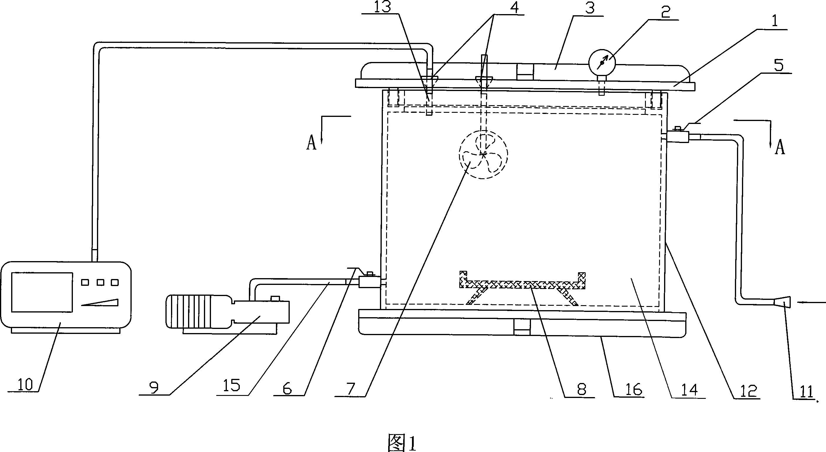
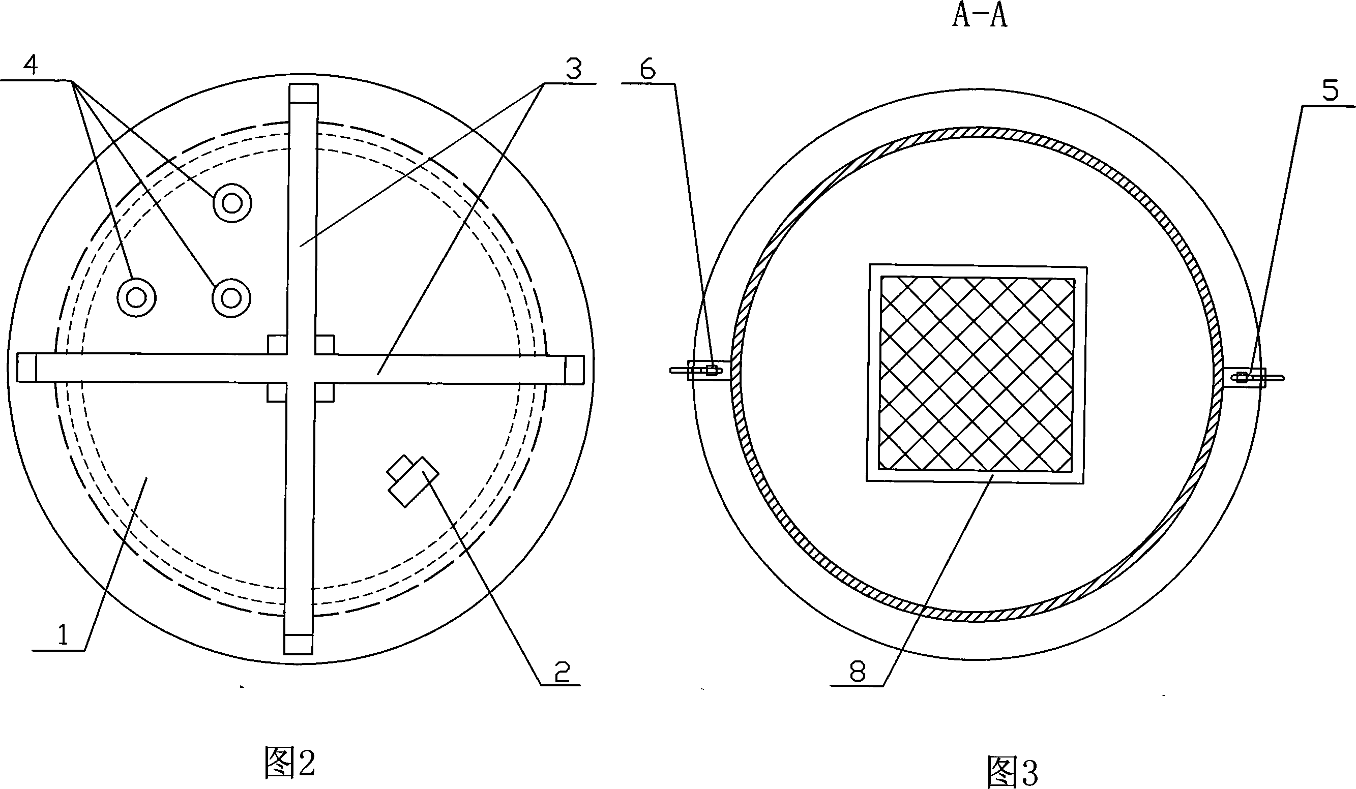
[0007] Embodiment 1: As shown in Figures 1 to 3, the test device for testing the degradation tail gas performance of new materials in this embodiment consists of a gas reaction chamber 12, an exhaust gas analyzer 10, a sensor probe 13, a vacuum pump 9, a fan 7, a negative Pressure gauge 2, intake valve 5, pumping / exhaust valve 6, connecting pipe 15, intake pipe 11 are made up; Described gas reaction chamber 12 is to be made of translucent material, and gas reaction chamber 12 is made of sealing cover 1 and reaction chamber container 14, the sealing cover 1 is airtightly connected with the reaction chamber container 14, the sensor probe 13 is plugged into the socket 4 on the sealing cover 1 and connected with the exhaust gas analyzer 10, the vacuum pump 9 and the bottom end of the reaction chamber container 14 pass through Connecting pipe 15 communicates, and described connecting pipe 15 is provided with suction / exhaust valve 6, and inlet pipe 11 is communicated with the upper e...

specific Embodiment approach 2

[0009] Embodiment 2: The gas reaction chamber 12 in this embodiment is made of organic glass material. The advantages of plexiglass are good light transmission, strong sealing, and easy observation, and can directly use natural light sources for experiments, which is closer to the actual environment, and also reduces the temperature impact caused by the use of ultraviolet light sources. Other compositions and connections are the same as in the first embodiment.

specific Embodiment approach 3

[0010] Embodiment 3: As shown in Fig. 1 and Fig. 2 , the seal cap 1 in this embodiment is provided with a seal cap cross-shaped stiffening beam 3 . It is designed in this way to strengthen its anti-deformation performance and ensure the vacuum working ability of the gas chamber. Other compositions and connections are the same as in the first embodiment.


PUM


Abstract

A tester for testing the performance of a new material degrading tail gas relates to a testing unit. The invention solves the problem of limited usage range, light-tightness of a gas reaction chamber, unstable testing result due to the change of temperature and environment, high cost of equipment and complicated structure, all of which are caused by that the prior test equipment does not have light conditions necessary for light-catalyzed reaction. A gas reaction chamber (12) of the invention is made from light transmissible materials, and consists of a cover gasket (1) and a reaction chamber vessel (14) which are in closed connection with each other; a sensor probe (13) is inserted in a jack (4) on the cover gasket (1), and is connected with a tail gas analyzer (10); a vacuum air pump (9) is connected with the bottom of the reaction chamber vessel (14) through a connecting hose (15). The invention has the advantages of unlimited usage range, direct use of solar light source as the reaction condition by the gas reaction chamber, accurate testing result, low cost of equipment and simple structure.

Description

technical field [0001] The present invention relates to a test device. Background technique [0002] With the research of new degradable tail gas materials such as photocatalysts, corresponding test and test equipment has also emerged. Among them, the test equipment for tail gas concentration has been developed and put into use. Due to the complexity of the situation, its related research and development work is still in its infancy. The following several test equipments are provided in the prior art: 1. The P7510 exhaust gas catalytic reaction device released by U.S. Cusson Company can be used to test the purification efficiency of the catalyst and the flow rate of the gas. Ceramic honeycomb carrier, put various catalysts to be tested on the carrier respectively, and test the concentration change of each harmful substance in the automobile exhaust flowing through the catalytic reactor, so as to obtain the catalytic conversion efficiency of each catalyst. However, the scop...

Claims


Application Information

Patent Timeline
Patent Type & Authority Applications(China)
IPC IPC(8): G01N33/00G01N31/00
Inventor 谭忆秋魏鹏周纯秀
Owner HARBIN INST OF TECH
Why Eureka
Try Eureka