
Round annular multiple freedom degrees ultrasound electric machine and electric excitation method thereof

A technology of ultrasonic motor and degree of freedom, applied in the direction of generator/motor, piezoelectric effect/electrostrictive or magnetostrictive motor, electrical components, etc., can solve the problem of limited application range, unfavorable miniaturization, and difficult reduction and other issues

Inactive Publication Date: 2008-04-16
NANJING UNIV OF AERONAUTICS & ASTRONAUTICS
View PDF0 Cites 24 Cited by
  • Summary
  • Abstract
  • Description
  • Claims
  • Application Information

AI Technical Summary

Problems solved by technology

In practice, the frequency of bending vibration is difficult to match with the frequency of longitudinal vibration, but the driving frequency of the motor can only be one, so the driving efficiency of the motor will be low, and the output performance of the motor will be affected
In addition, because the rod-type multi-degree-of-freedom motor utilizes the two-bend vibration mode and longitudinal vibration mode, as well as the limitation of the stator assembly size, its axial size is difficult to reduce, which is not conducive to miniaturization, so the application range is limited

Method used


Image

  • Round annular multiple freedom degrees ultrasound electric machine and electric excitation method thereof
  • Round annular multiple freedom degrees ultrasound electric machine and electric excitation method thereof
  • Round annular multiple freedom degrees ultrasound electric machine and electric excitation method thereof

Examples


Embodiment Construction

[0015] The specific embodiment and working principle of the present invention are described according to the accompanying drawings.

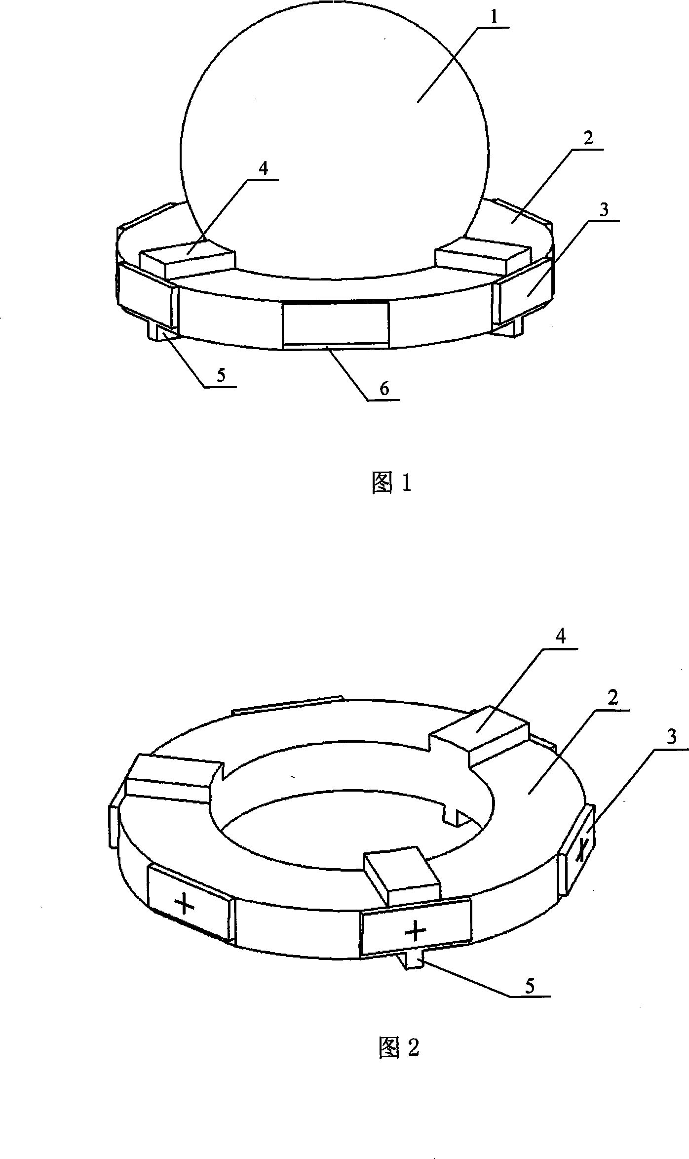
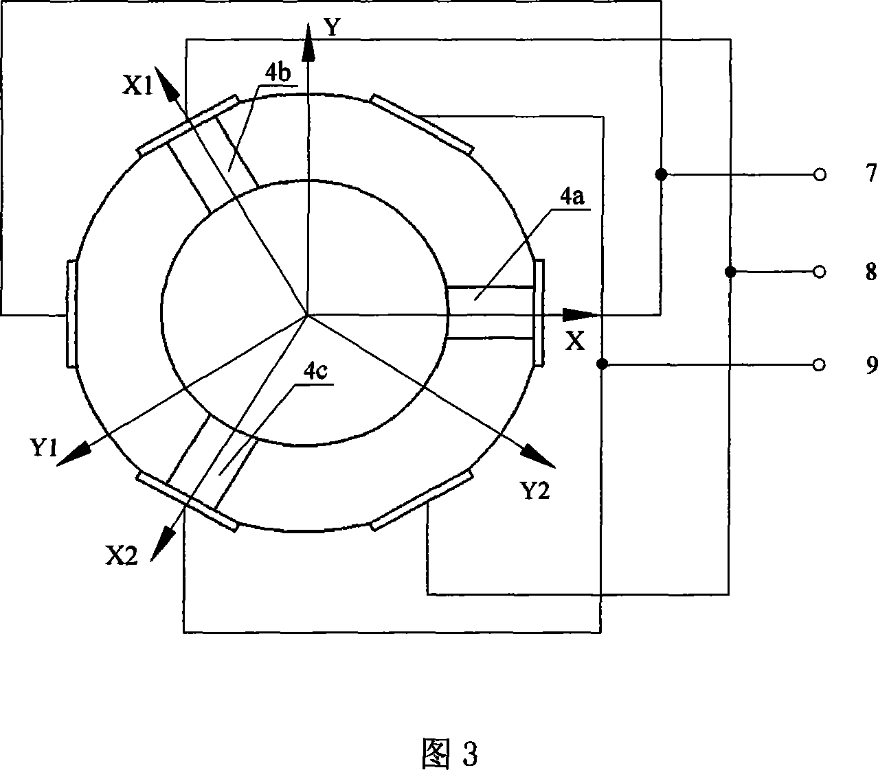
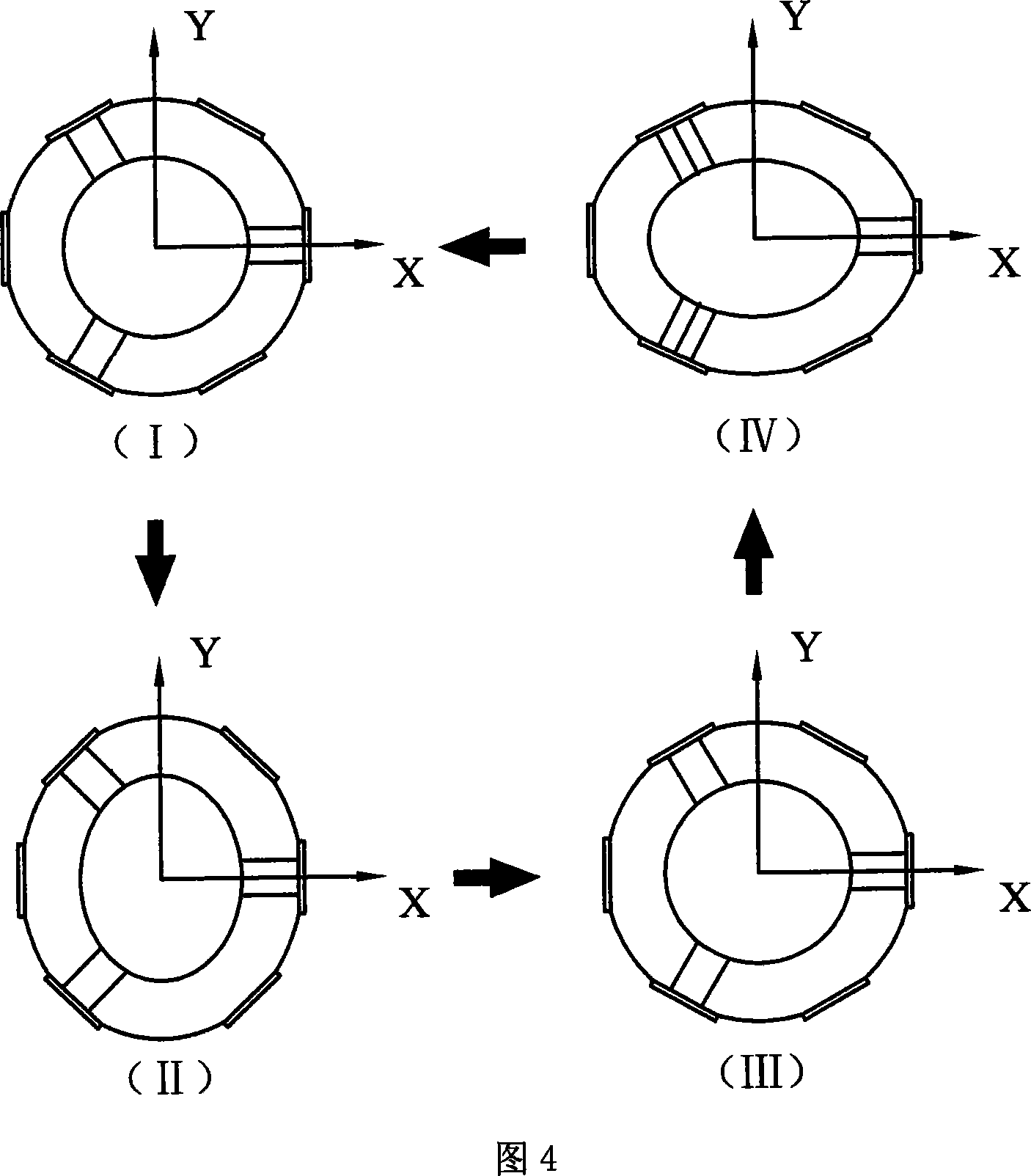
[0016] As shown in FIG. 1 , the circular multi-degree-of-freedom ultrasonic motor of the present invention is mainly composed of a rotor and a stator. The rotor is a spherical rotor 1; the stator is a metal ring 2, and six piezoelectric ceramic sheets 3 are uniformly pasted on its side, and the two opposite piezoelectric ceramic sheets are aligned in parallel; the upper end surface of the ring stator has three upper bosses 4. They are evenly distributed along the circumferential direction, and the upper boss is at the same position as the platform 6 on which three piezoelectric ceramic sheets are pasted, which are used to support and drive the spherical rotor; the rotor provides the preset required between the stator and the rotor through its own weight. Pressure; the lower end surface of the ring stator also has three small bosses 5, and their ...


PUM


Abstract

The invention relates to a ring-type multi-degree-of-freedom ultrasonic motor and an electric excitation method, pertaining to the field of ultrasonic motors. The ultrasonic motor comprises a rotor and a stator. The invention is characterized in that the rotor is a spherical rotor (1); the stator is a metal ring (2), and six piezo-electric ceramic pieces (3) are affixed on the flank of the ring stator; three upper bosses (4) are evenly distributed on the periphery of the upper end-face of the ring stator and arranged at the same position of the platform (6) affixed with ceramic pieces to support and drive the spherical stator; the rotor provides the prepress force required by the stator and the rotor; three small bosses (4) corresponding to the positions of the upper bosses (4) are also arranged on the lower end-face of the ring stator to support the whole motor. When the driving signal provides power supply to any two piezo-electric ceramic pieces (3) opposite to each other, the two flexural vibration modes in the face of the stator can be excited out to produce standing waves and drive the spherical rotor to round the spherical center of the rotor and rotate around the axial line parallel with the two piezo-electric ceramic pieces. The ultrasonic motor can realize the rotation of a plurality of rotating shafts; the invention has the advantages of a simple structure, a small size, high efficiency, reliable operation, etc.

Description

Technical field: [0001] The invention relates to an annular multi-degree-of-freedom ultrasonic motor and an electric excitation method, belonging to the field of ultrasonic motors. Background technique: [0002] Ultrasonic motor is a new concept power device that utilizes the inverse piezoelectric effect of piezoelectric material and ultrasonic vibration of elastic body. At present, the multi-degree-of-freedom ultrasonic motor is mostly a rod-type stator and a spherical rotor structure. The rod-type stator uses two bending vibrations and one longitudinal vibration to realize the rotation of the three rotation axes of the rotor. In practice, the frequency of bending vibration is difficult to match with the frequency of longitudinal vibration, but the driving frequency of the motor can only be one, so the driving efficiency of the motor will be low, and the output performance of the motor will be affected. In addition, because the rod-type multi-degree-of-freedom motor utiliz...

Claims


Application Information

Patent Timeline
IPC IPC(8): H02N2/12
Inventor 赵淳生张健滔金家楣
Owner NANJING UNIV OF AERONAUTICS & ASTRONAUTICS
Learn More