Drum-type mixer

A mixer and drum-type technology, applied in cement mixing devices, chemical instruments and methods, clay preparation devices, etc., can solve problems such as difficult cleaning of solidified materials, uneven mixing, and affecting quality, and achieve high use value and promotion value , uniform mixing, simple structure

Inactive Publication Date: 2008-04-23
孙文霞
View PDF0 Cites 5 Cited by
  • Summary
  • Abstract
  • Description
  • Claims
  • Application Information

AI Technical Summary

Problems solved by technology

Moreover, the equipment is complicated, the efficiency is low, the stirring is uneven, and the solidification accumulated in the equipment is difficult

Method used


Image

  • Drum-type mixer

Examples


Embodiment Construction

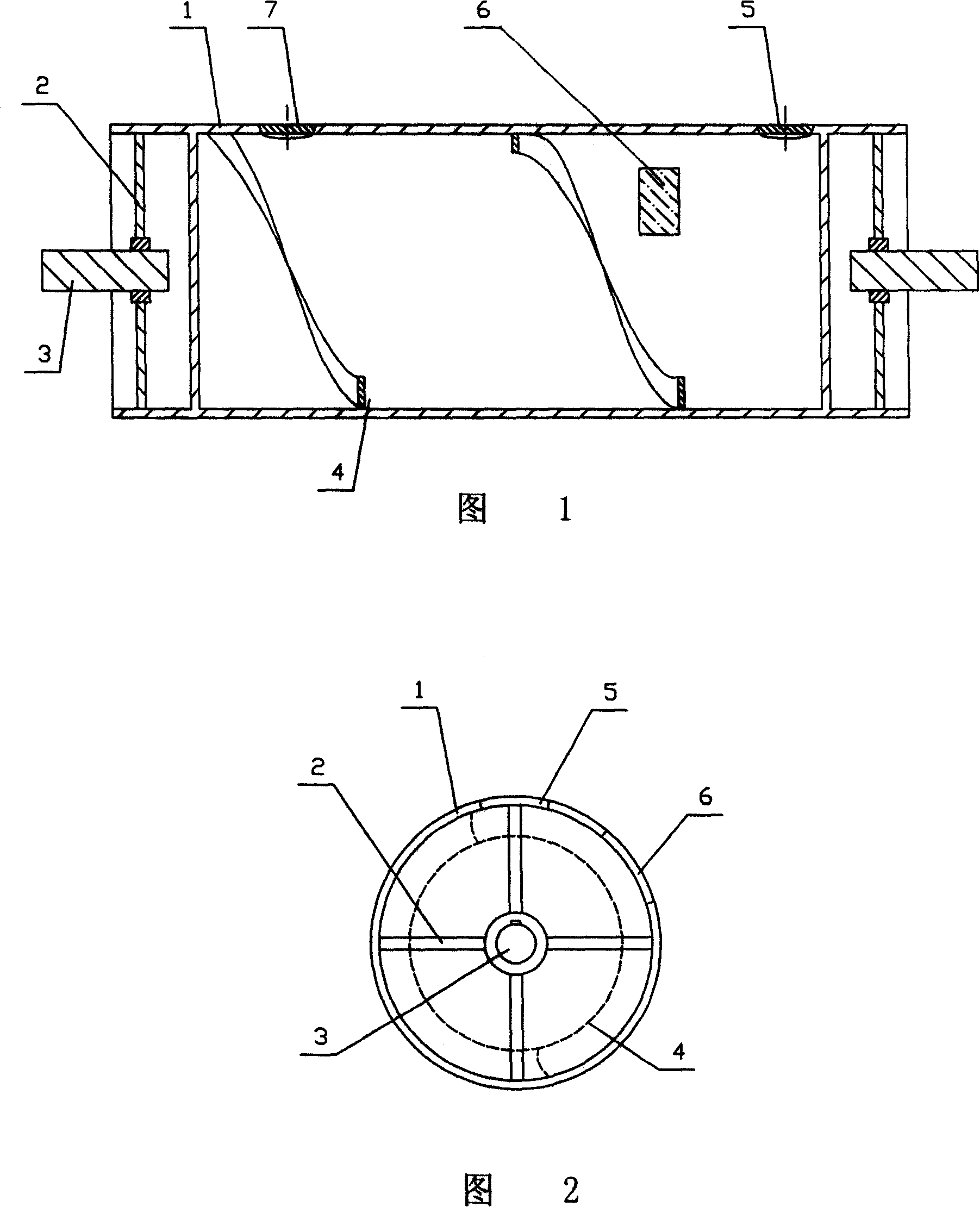
[0015] Embodiment, as shown in Fig. 1, Fig. 2, the drum agitator comprises cylinder body 1, and the two ends of cylinder body 1 are welded support frame 2, and the welding point of support frame 2 is evenly distributed in the inner side of cylinder body 1, and support frame 2 is keyed to connect the drive shaft 3, the inner side wall of the cylinder 1 is welded with a continuous spiral blade 4, one end of the cylinder 1 is provided with a material inlet 5, the other end of the cylinder 1 is provided with a material outlet 7, and the cylinder 1 has at least An observation window 6 is provided.

[0016] A spiral guide groove is formed between the spiral blades 4. When the material enters the cylinder 1 from the feed port, the material will move along the channel surrounded by the cylinder 1 and the spiral blade 4. Every time the cylinder 1 rotates, the spiral The blade 4 pushes the material toward the outlet by one pitch. This propulsion movement not only plays the role of conv...


PUM


Abstract

The present invention discloses a drum-type stirrer. It includes a drum body, two ends of the described drum body are fixedly connected with a supporting frame, the described supporting frame is fixedly connected with a drive shaft, in the described drum body interior a continuous helical blade is fixedly set, one end of said drum body is equipped with a material inlet, another end of said drum body is equipped with a material outlet, and on the drum body an observation window is set.

Description

technical field [0001] The invention relates to a construction machine, in particular to a drum type agitator. Background technique [0002] At present, in the construction industry, the mixing equipment used can only carry out quantitative mixing, and cannot carry out continuous automatic production, and the output is low. Due to the different conditions of stirring each time, such as stirring time, the ratio of materials, etc., there are also differences in the specifications of the obtained mixture. Moreover, the equipment is complicated, the efficiency is low, the stirring is uneven, and the solidified matter accumulated in the equipment is difficult to clean up. The falling off of the solidified matter during the stirring process will affect the normal stirring and the quality of the stirred mixture. Contents of the invention [0003] The purpose of the present invention is to provide a drum type agitator capable of continuous automatic production, uniform stirring a...

Claims


Application Information

Patent Timeline
IPC IPC(8): B28C5/22
Inventor 孙文霞
Owner 孙文霞
Why Eureka
Try Eureka