Ball bearing internal ditch automatic measurement feeding device

An automatic measurement, ball bearing technology, applied in the direction of transportation and packaging, conveyor objects, etc., can solve the problems of large changes in measurement accuracy and quantity, and achieve the effect of high precision, product quality and quantity assurance, and fast speed

Inactive Publication Date: 2011-07-27
HEILONGJIANG UNIV
View PDF0 Cites 0 Cited by
  • Summary
  • Abstract
  • Description
  • Claims
  • Application Information

AI Technical Summary

Problems solved by technology

At present, manual feeding is used for conventional measurement, which is affected by technical factors and environmental factors, and the accuracy and quantity of measurement vary greatly.

Method used


Image

  • Ball bearing internal ditch automatic measurement feeding device
  • Ball bearing internal ditch automatic measurement feeding device
  • Ball bearing internal ditch automatic measurement feeding device

Examples


Embodiment 1

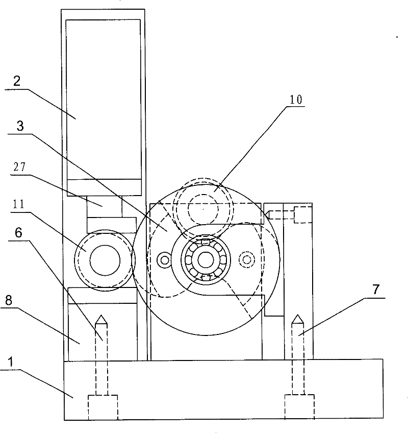
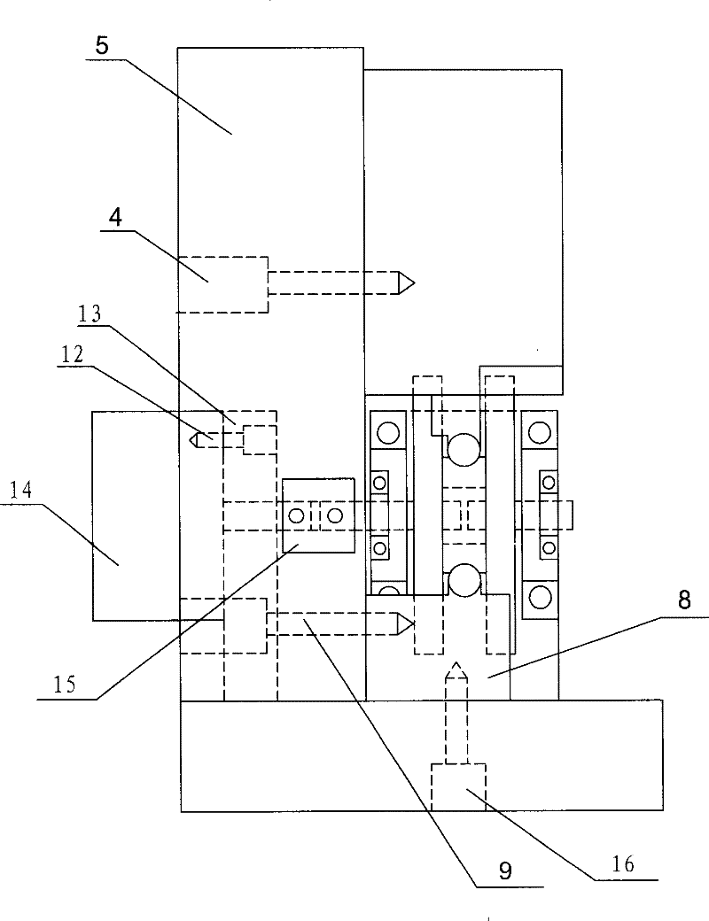
[0019] The automatic feeding device for ball bearing inner groove measurement comprises: a column 5 fixed on the measurement platform 1 with fasteners 6, a measuring mechanism 2 is fixed on the column 5 by fasteners 4, and the measurement An upper measuring slideway 27 is installed in the mechanism 2 , a loading and unloading device 3 is fixed on the measuring platform 1 , and a lower measuring slideway 8 is fixed on the measuring platform 1 .

Embodiment 2

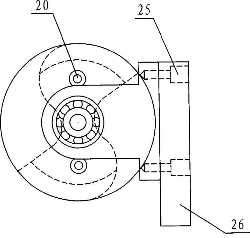
[0021] The above-mentioned automatic feeding device for ball bearing inner groove measurement, the described loading and unloading device 3 includes a feed wheel 17, a left side plate 18 of the feed wheel, and a right side plate 19 of the feed wheel, and the three are connected by a fastener 20 Together, the long axis end of the left side plate 18 of the feed wheel is connected with the left bearing 22, the left bearing pad seat 21, the short axis of the right side plate 19 of the feed wheel is connected with the right bearing 24, the right bearing The shoe seat 23 is connected, the left bearing shoe seat 21 and the right bearing shoe seat 23 are fixed on the bearing shoe seat support plate 26 by the fastener 25, and the bearing shoe seat support plate 26 is fixed by the fastener 7 is fixed on the measuring platform 1.

Embodiment 3

[0023] In the above-mentioned automatic feeding device for ball bearing inner groove measurement, the shape of the surface of the inner sleeve of the bearing pushed by the feed wheel and the measurement surface of the upper and lower measurement slideways is an arc whose radius is smaller than the radius of the steel ball in the bearing, so The feed wheel is involute toothed, the long axis of the left side plate 18 of the feed wheel is connected to the stepper motor 14 through a coupling 15, and the stepper motor 14 is fixed by a fastener 12 On the stepper motor support 13 , the stepper motor support 13 is fixed on the measurement platform 1 with fasteners 16 . Make sure that each workpiece is sent to a relatively fixed position on the measurement surface.

[0024] Work Engineering Description:

[0025] In the above-mentioned automatic feeding device for ball bearing inner groove measurement, the workpiece 10 to be detected enters the feed wheel 17 under the action of gravity...


PUM


Abstract

The present invention relates to a ball bearing inner groove automatic measurement charging device. When the ball bearing is assembled by using matched sleeve, the existent conventional measurement uses manual charging method, its measurement accuracy and quantity change are large, if the invented ball bearing inner groove size measurement automatic charging device is used for making charging, itcan be regulated only once, and can implement automatic charging, and can ensure product quality and product quantity. The composition of said product includes: upright column fixed on the measurement platform, measuring mechanism fixed on the described upright column, upper measurement slideway mounted in the described measuring mechanism, charging and discharging device fixed on the described measurement platform and lower measurement slideway fixed on the described measurement platform. Said product can be used for measuring ball bearing inner sleeve groove size.

Description

Technical field: [0001] The invention relates to an automatic feeding device for measuring the channel size of an inner sleeve of a ball bearing. Background technique: [0002] When the ball bearing is assembled with a matching sleeve (matching), it needs to be determined according to the inner sleeve channel size, the outer sleeve channel size, the size of the ball ball, the clearance between the ball ball and the inner sleeve, the outer sleeve (oil gap), and the grade of the bearing. for assembly. Therefore, the sorting accuracy and speed of the inner and outer outer grooves of small and medium-sized ball bearings are very important. The automatic feeding device for ball bearing inner groove size measurement is designed for automatic detection of inner groove size. At present, manual feeding is used for routine measurement, and the accuracy and quantity of measurement vary greatly due to technical factors and environmental factors. Invention content: [0003] The obje...

Claims


Application Information

Patent Timeline
Patent Type & Authority Patents(China)
IPC IPC(8): B65G47/74B65G47/84
Inventor 刘英涛刘贺滨
Owner HEILONGJIANG UNIV
Why Eureka
Try Eureka