Device for harmlessly conversing plastic rubber garbage to combustible gas

A gas device and garbage technology, applied in the field of plastic garbage recycling equipment, can solve the problems of non-renewable value, rubber garbage polluting the environment, etc., and achieve the effects of outstanding environmental and social benefits, significant economic benefits, and simple structure

Inactive Publication Date: 2008-04-23
张松垒 +2
View PDF0 Cites 3 Cited by
  • Summary
  • Abstract
  • Description
  • Claims
  • Application Information

AI Technical Summary

Problems solved by technology

At present, in order to solve the problem of rubber waste polluting the environment, the only way is to produce reclaimed rubber products. However, after the reclaimed rubber products reach the end of their service life, they usually have no regeneration value and can only be discarded. The discarded reclaimed rubber products become completely useless garbage

Method used


Image

  • Device for harmlessly conversing plastic rubber garbage to combustible gas
  • Device for harmlessly conversing plastic rubber garbage to combustible gas

Examples


Embodiment 1

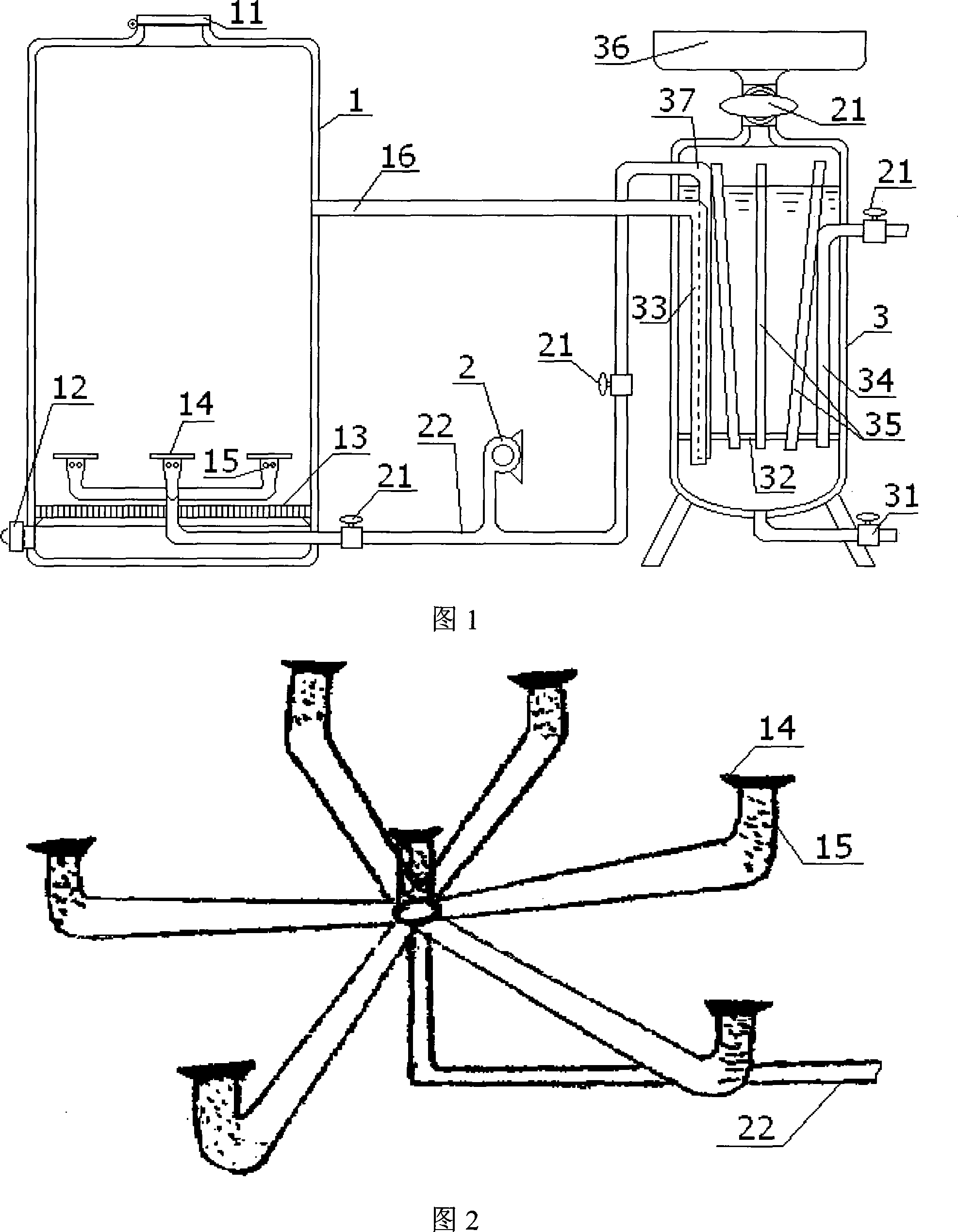
[0023] Embodiment 1, as shown in Figure 1, the device for the harmless conversion of plastic waste into combustible gas according to the present invention includes a gasification furnace and a cooling liquid remover with cooling and gas-liquid separation functions. The gasification furnace includes an upper end with a feeding port 11, a lower end A vertical furnace body 1 with a slagging outlet 12, the furnace body 1 is equipped with a furnace grate 13 above the slagging outlet 12, and an air nozzle 15 with a cover plate 14 on the top and a gas injection port on the side of the furnace grate 13 is arranged. The nozzle 15 is connected to the air blower 2 through the air regulating valve 21 and the air pipe 22, and the upper side of the furnace body 1 is connected with an air outlet pipe 16; the air outlet pipe 16 is further connected to the cooling liquid remover.

[0024]The cooling liquid remover includes a vertical tank body 3 with a drain valve 31 at the bottom, a partition ...

Embodiment 2

[0025] Embodiment two, as shown in Figure 2, its difference with embodiment one is that described air nozzle 15 is that a central air nozzle 15 is arranged in the middle, and six peripheral air nozzles 15 are evenly arranged on the circumference of central air nozzle 15, Air nozzle 15 top still has cover plate 14.

Embodiment 3

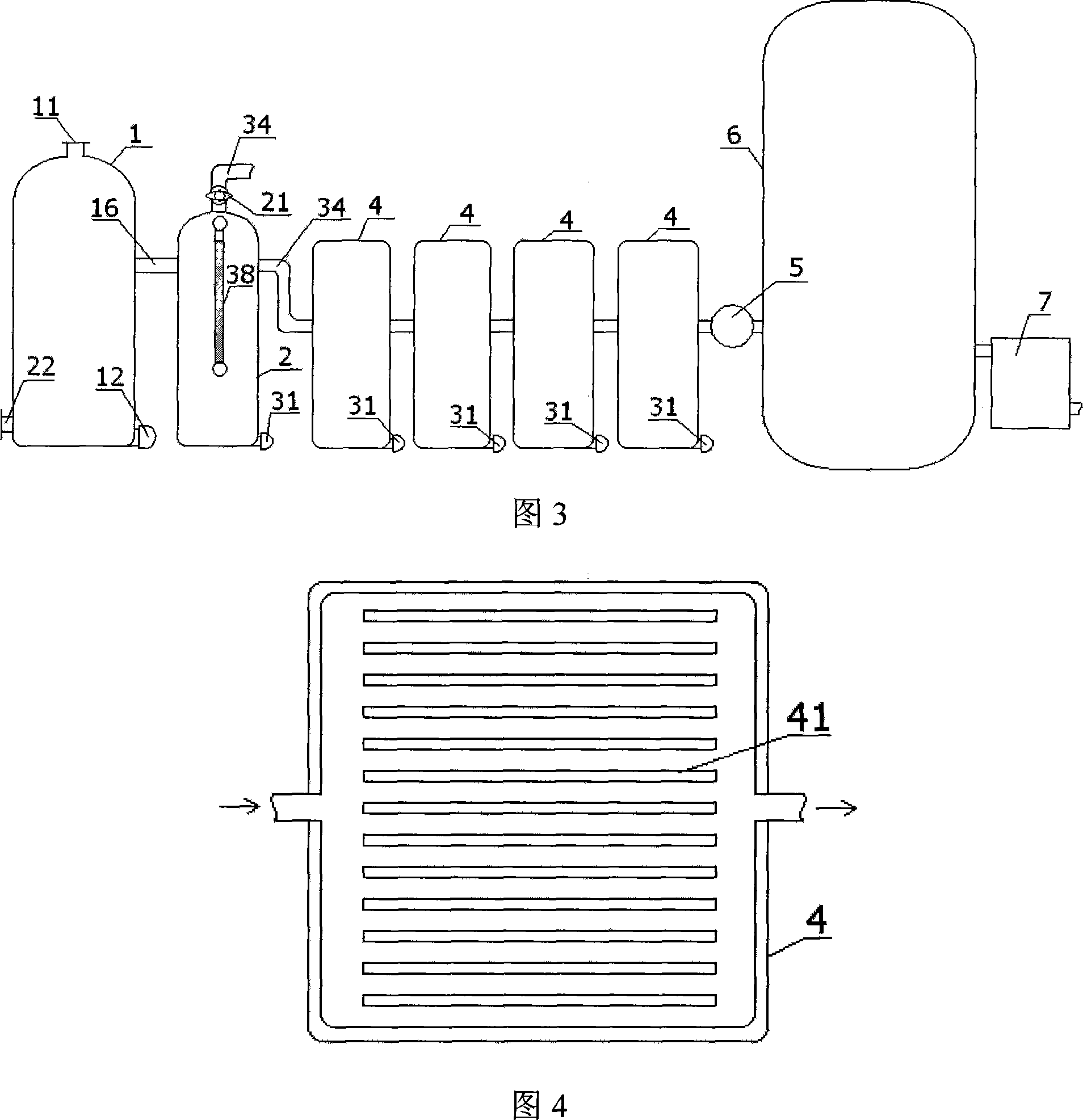
[0026] Embodiment 3, as shown in Figures 3 and 4, the difference between the harmless conversion of plastic waste and combustible gas device of the present invention and Embodiment 2 is that a water level gauge 38 is installed on the vertical tank body 3 of the cooling eliminator, and the tank body 3 The top is connected to a clean air pipe 34 through an air regulating valve 21 . After the side cleaning air pipe 34 of the cooling deliquidator is connected in series with four buffer adsorption tanks 4 with a drain valve 31 at the bottom, the pressurized cooling pump 5 is further connected to the gas storage tank 6 with a drain valve 31 at the bottom. The gas storage tank 6 is connected to the liquefied gas storage tank through the liquefaction device 7; the buffer adsorption tank 4 is built with glass adsorption plates 41 densely distributed in the same direction as the air flow.


PUM


Abstract

The apparatus for converting waste plastic and rubber into combustible gas includes one gasifying furnace and one cooling liquid trap possessing both cooling and gas-liquid separating functions. The gasifying furnace is one vertical furnace with top material inlet, lower slag outlet, furnace grill over the slag outlet, one top air nozzle connected through one air regulating valve and air pipeline to one air blower, and one gas outlet pipe set in the middle part and connected to the cooling liquid trap. The apparatus can convert waste plastic and rubber into combustible gas capable of being applied as fuel and chemical material while obtaining ash capable of being used as trace element fertilizer and liquid capable of being reused. It has high conversion rate, no secondary pollution and other advantages, and makes it possible to eliminate white pollution radically.

Description

technical field [0001] The invention relates to a recycling equipment for plastic waste, in particular to a device for harmless transformation of plastic waste into combustible gas. Background technique [0002] At present, in order to solve the problem of plastic waste polluting the environment, someone has developed a plastic waste refining technology, which is to strictly classify and clean the recycled plastic waste, and then put it into a degradation furnace with a catalyst for thermal decomposition to produce Diesel: It obviously has the problems of sorting plastic waste, high cleaning costs, and easy catalyst poisoning. So far, it has not been promoted. At present, in order to solve the problem of rubber waste polluting the environment, the only way is to produce reclaimed rubber products. However, after the reclaimed rubber products reach the end of their service life, they usually have no regeneration value and can only be discarded. The discarded reclaimed rubber ...

Claims


Application Information

Patent Timeline
Patent Type & Authority Applications(China)
IPC IPC(8): C10B53/07B09B3/00
CPCY02P20/143
Inventor 张松垒
Owner 张松垒
Why Eureka
Try Eureka