
System and method for realizing stable combustion and carbon emission reduction of thermal power plant by utilizing blending combustion of biofuel ethanol

A bio-fuel, fuel ethanol technology, applied in the direction of using a variety of fuel combustion, combustion methods, using block fuel and liquid fuel combustion, etc., can solve the problems of high economic cost, boiler flameout, and no help in carbon emission reduction, etc. achieve the effect of increasing economic benefits

Pending Publication Date: 2020-11-17
HEPU ENERGY ENVIRONMENTAL TECHNOLOGY CO LTD
View PDF2 Cites 2 Cited by
  • Summary
  • Abstract
  • Description
  • Claims
  • Application Information

AI Technical Summary

Problems solved by technology

If there is no combustion-supporting or combustion-stabilizing measures, it is very easy for the boiler to stall
At present, the economic cost of relying on oil injection to stabilize combustion is relatively high, and it does not help carbon emission reduction.

Method used


Image

  • System and method for realizing stable combustion and carbon emission reduction of thermal power plant by utilizing blending combustion of biofuel ethanol
  • System and method for realizing stable combustion and carbon emission reduction of thermal power plant by utilizing blending combustion of biofuel ethanol
  • System and method for realizing stable combustion and carbon emission reduction of thermal power plant by utilizing blending combustion of biofuel ethanol

Examples


Embodiment 1

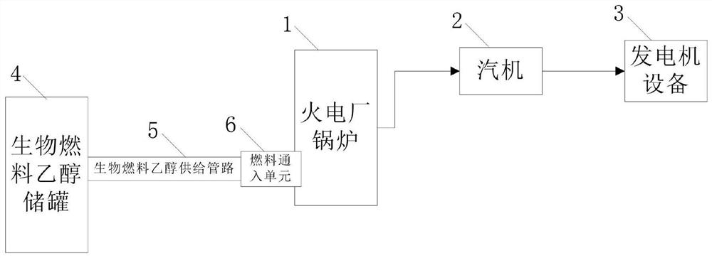
[0051] A thermal power plant blending biofuel ethanol combustion stable and carbon emission reduction system, such as figure 1 As shown, it includes a thermal power plant boiler 1, a steam turbine 2 and a generator equipment 3, the thermal power plant boiler 1 is connected to the steam turbine 2, the steam turbine 2 is connected to the generator equipment 3, and the thermal power plant blends biofuel ethanol for stable combustion And the carbon emission reduction system also includes a biofuel ethanol storage tank 4, a biofuel ethanol supply pipeline 5 and a fuel inlet unit 6, the fuel inlet unit 6 is arranged on the thermal power plant boiler 1, and the biofuel ethanol storage tank 4 passes through the biofuel The ethanol supply pipeline 5 is connected to the fuel inlet unit 6, and the biofuel ethanol storage tank 4 stores the biofuel ethanol converted from any one of grain, biomass, lignocellulose, and sugarcane sugar plants, It is supplied to the boiler 1 of the thermal pow...

Embodiment 2

[0053] like figure 2 As shown, on the basis of Embodiment 1, the fuel inlet unit 6 includes a multi-fuel burner 61, and a combustion gun supply pipe 611 is arranged on the multi-fuel burner 61, and the biofuel ethanol supply pipeline 5 will The biofuel ethanol storage tank 4 is connected to the combustion gun supply pipe 611 of the multi-fuel burner 61 arranged on the thermal power plant boiler 1 .

Embodiment 3

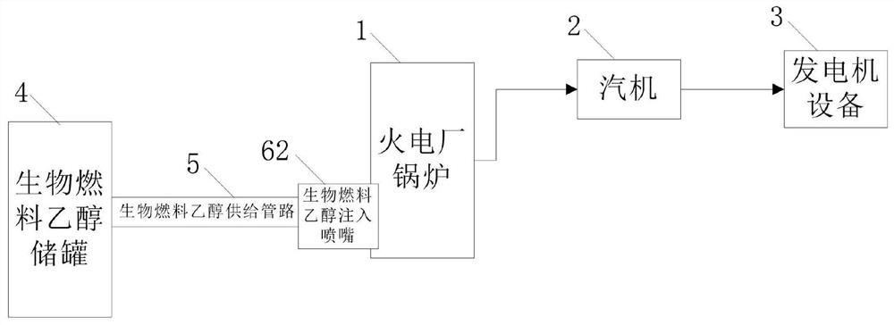
[0055] like image 3 As shown, on the basis of Embodiment 1, the fuel inlet unit 6 includes a biofuel ethanol injection nozzle 62, and the biofuel ethanol supply pipeline 5 connects the biofuel ethanol storage tank 4 with the biofuel ethanol provided on the boiler 1 of the thermal power plant. Fuel ethanol injection nozzle connection.


PUM


Abstract

The invention discloses a system and a method for realizing stable combustion and carbon emission reduction of a thermal power plant by utilizing blending combustion of biofuel ethanol. The system forrealizing stable combustion and carbon emission reduction of the thermal power plant by utilizing blending combustion of the biofuel ethanol comprises a thermal power plant boiler, a steam turbine and generator equipment, wherein the thermal power plant boiler is connected to the steam turbine, and the steam turbine is connected to the generator equipment; the system for realizing stable combustion and carbon emission reduction of the thermal power plant by utilizing blending combustion of the biofuel ethanol further comprises a biofuel ethanol storage tank, a biofuel ethanol supply pipelineand a multi-fuel combustor or a biofuel ethanol injection nozzle, wherein the ethanol injection nozzle is arranged on the thermal power plant boiler; the biofuel ethanol is connected to the multi-fuelcombustor or the biofuel ethanol injection nozzle through the biofuel ethanol supply pipeline; and the biofuel ethanol storage tank is used for storing the biofuel ethanol converted from any one of grain, biomass, lignocellulose and sugarcane and glucide plants and supplying the biofuel ethanol to the thermal power plant boiler for blending combustion, so that the functions of combustion supporting, stable combustion or carbon emission reduction of the boiler are achieved.

Description

technical field [0001] The invention relates to the fields of stable combustion and carbon emission reduction of boilers in thermal power plants, in particular to a system for stable combustion and carbon emission reduction of biofuel mixed with ethanol in thermal power plants and a carbon emission reduction control method. Background technique [0002] Coal-fired thermal power plants are large carbon emitters. How to reduce the carbon emission intensity of large coal-fired thermal power plants is a huge obstacle facing the thermal power industry in the future. If carbon emissions cannot be reduced, many large thermal power plants will face shutdown and loss situation. Domestic patent 201810673269.4 discloses a multi-generation peak-shaving power station system, that is, using coal gasification to support combustion when the boiler in the power plant is low-load, the flexibility of peak-shaving power generation will be greatly improved, and the fuel cost will not increase. ...

Claims


Application Information

Patent Timeline
IPC IPC(8): F23C1/10F23C5/08F23K5/02F23K5/14
CPCF23C1/10F23C5/08F23K5/02F23K5/147
Inventor 崔华杨豫森陈辉
Owner HEPU ENERGY ENVIRONMENTAL TECHNOLOGY CO LTD
Learn More