
Outer watchdog circuit

A technology of watchdog and watchdog chip, which is applied in the direction of electrical digital data processing, instrumentation, error detection/correction, etc. It can solve the problems that the program decompression cannot be executed normally, and MAX706 does not exist.

Active Publication Date: 2008-04-23
VERTIV CORP
View PDF0 Cites 22 Cited by
  • Summary
  • Abstract
  • Description
  • Claims
  • Application Information

AI Technical Summary

Problems solved by technology

Currently commonly used watchdog devices are ADI’s ADM706 and MAXIM’s MAX706. The pin packages of these two chips are compatible, and the output reset pulse width is 200ms. The biggest difference between them is that ADM706 can be set by setting the WDI pin to High-impedance state is disabled (not enabled or disabled), but MAX706 does not have this function
In the embedded system application of 32bit RISC CPU, it is generally not desirable to enable the watchdog when the system is started. The reason is that the embedded system generally executes the decompression action of the program when the It takes a long time to execute this decompression algorithm, and cannot perform periodic dog feeding, so it is generally not desirable to enable the watchdog when the embedded system starts; otherwise, because the CPU does not feed the dog, the watchdog will The reset signal is continuously given, so that the program decompression cannot be executed normally; therefore, some existing watchdog chips cannot meet this requirement

Method used


Image

  • Outer watchdog circuit
  • Outer watchdog circuit
  • Outer watchdog circuit

Examples


Embodiment 1

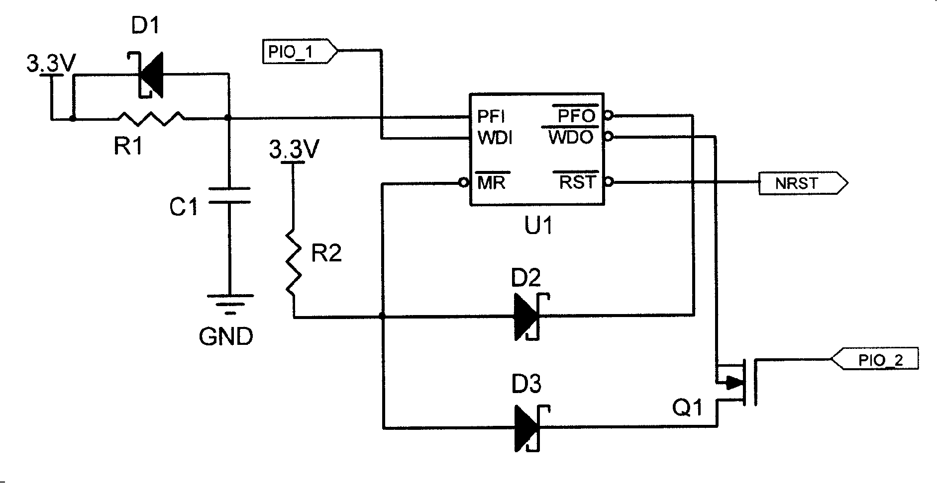
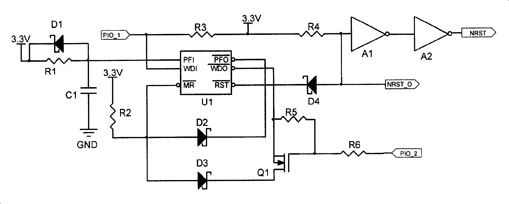
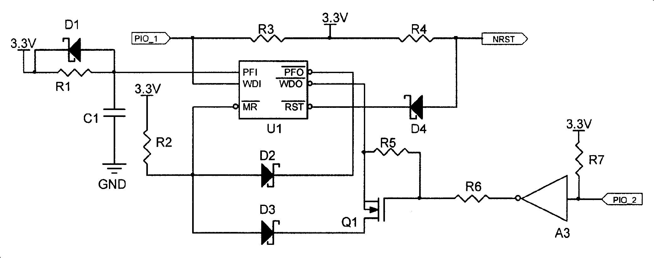
[0028] figure 1 It is the schematic diagram (1) of the external watchdog circuit of Embodiment 1 of the present invention. In this figure, an RC circuit is used to adjust the reset pulse width output by the watchdog chip U1. The external watchdog circuit of the present invention includes a watchdog Chip U1, RC circuit, second resistor R2, second diode D2, and a switch unit including a third diode D3 and a MOS transistor Q1, wherein the MOS transistor Q1 is used as a controllable switch; the watchdog chip U1 The dog feeding signal input terminal WDI is used to connect the dog feeding signal source (such as the CPU dog feeding signal), and its reset signal output terminal RST is used to output the reset signal NRST.

[0029] The RC circuit includes a first resistor R1, a first capacitor C1 and a first diode D1, the first resistor R1 and the first capacitor C1 form a first-order resistance-capacitance circuit, and one end of the first resistor R1 is connected to a power supply of...

Embodiment 2

[0043] Figure 5 The circuit schematic shown with figure 1 The circuit schematic shown differs in that, Figure 5 Use the eighth resistor R8 to replace figure 1 in the second diode D2, and with Figure 5 In place of the ninth resistor R9 in the figure 1 In the third diode D3, wherein, the two ends of the eighth resistor R8 are respectively connected to the power-off detection output terminal PFO and the reset input terminal MR of the watchdog chip U1; the two ends of the ninth resistor R9 are respectively It is connected to the reset input terminal MR of the watchdog chip U1 and the drain of the MOS transistor Q1. Through the voltage divider circuit formed by the second resistor R2 and the eighth resistor R8, the power-off detection output terminal PFO of the watchdog chip U1 is pulled low or its reset signal input terminal MR is pulled high, and the second resistor R2 and the ninth resistor The voltage divider circuit formed by R9 makes the dog feeding signal output term...


PUM


Abstract

The circuit comprises: a watch-dog chip (U1) whose dog-feeding input end (WDI) is connected to the dog-feeding signal source, and whose reset output end (RST) is used for outputting a reset signal; a first order RC circuit connected to the power failure detection input (PFI) of the watch-dog chip (U1) and used for adjusting the time length in which the input voltage of said PFI is made to equal to the reference voltage; the power failure detection output end (PFO) is connected to the reset input end (MR); the state of both PFO and MR are the same high level or low level. The invention can be used for disabling the watch-dog when the CPU is powered on.

Description

[technical field] [0001] The invention relates to a relatively general processor watchdog reset circuit, in particular to an external watchdog circuit with adjustable reset pulse width. [Background technique] [0002] Due to the wide application of 32bit RISC CPU (Reduced Instruction Set Computing CPU), the Firmware (firmware) on it is becoming more and more complex, which puts forward higher requirements for the reliability of the embedded system, so the external The watchdog is also widely used in circuit design. Currently commonly used watchdog devices are ADI’s ADM706 and MAXIM’s MAX706. The pin packages of these two chips are compatible, and the output reset pulse width is 200ms. The biggest difference between them is that ADM706 can be set by setting the WDI pin to High-impedance state is disabled (not enabled or disabled), but MAX706 does not have this function. In the embedded system application of 32bit RISC CPU, it is generally not desirable to enable the watchdo...

Claims


Application Information

Patent Timeline
IPC IPC(8): G06F11/00
Inventor 陈巍严宁宁包培友蔡宁果冯鸣吴小华
Owner VERTIV CORP
Learn More