Hub-shape knife and cutting device

A cutting device and cutting tool technology, which is applied in the manufacture of electrical components, circuits, semiconductors/solid-state devices, etc., can solve problems such as difficult disassembly and assembly, and achieve the effects of improving productivity, ensuring disassembly and assembly, and ensuring cutting efficiency

Inactive Publication Date: 2008-04-30
DISCO CORP
View PDF1 Cites 2 Cited by
  • Summary
  • Abstract
  • Description
  • Claims
  • Application Information

AI Technical Summary

Problems solved by technology

However, this kind of measure requires a substantial change in the shape of the abutment from the existing product, and it is necessary to maintain at least the same level of processability as compared with the existing product, so it cannot be regarded as an efficient specification change
In addition, the protruding part of the base is an obstacle when detaching from the main shaft, but it is difficult to detach without the protruding part

Method used


Image

  • Hub-shape knife and cutting device
  • Hub-shape knife and cutting device
  • Hub-shape knife and cutting device

Examples


Embodiment Construction

[0036] One embodiment of the present invention will be described below with reference to the drawings.

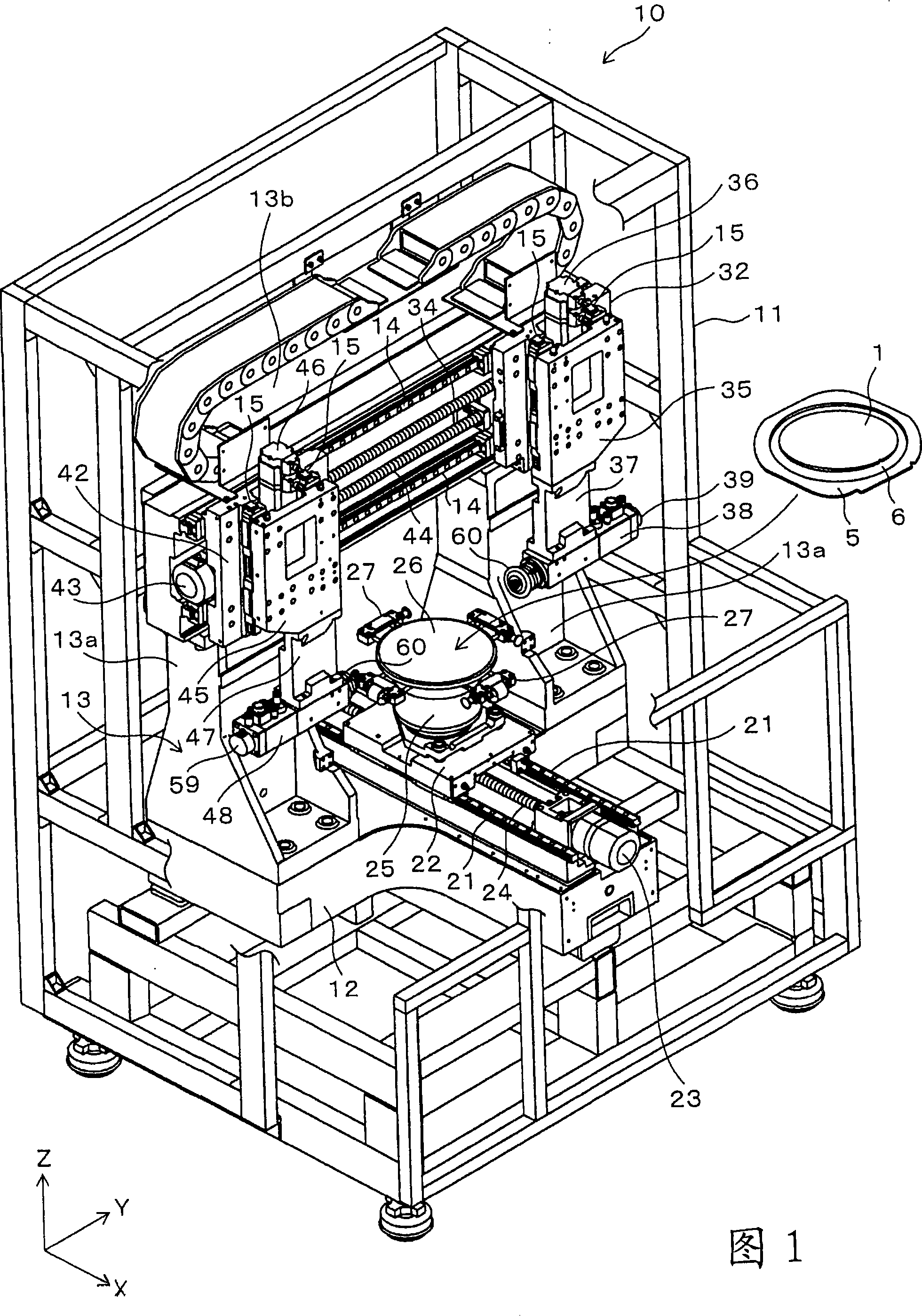
[0037] FIG. 1 shows a dual-axis opposed cutting device 10 according to one embodiment. Reference numeral 11 in FIG. 1 is the main frame of the whole device, a base frame 12 is fixed on the bottom inside the main frame 11 , and a portal column 13 is fixed on the base frame 12 . A pair of X-axis linear guides 21 extending in the X-axis direction are provided at the center of the base frame 12 , and X-axis sliders 22 are slidably attached to these X-axis linear guides 21 . The X-axis slider 22 is reciprocated along the X-axis linear guide 21 by the ball screw feed mechanism 24 driven by the X-axis feed motor 23 . A disk-shaped suction table 26 is provided on the X-axis slider 22 via a suction table base 25 .

[0038] The suction cup table 26 is rotatably supported on the suction cup table base 25 about the Z-axis direction (vertical direction), and is driven to rotate clockw...


PUM


Abstract

The invention provides a hub-shaped cutter and a cutting device which is a two-axle opposite type with an opposite positioned main axles assembly, remaining the assembly-disassembly character of the hub-shaped cutter, and decreasing the space of the opposite positioned hub-shaped cutters to the best of it's abilities.The hub-shaped cutters(60) are mounted on each main axle (52) of two group of main axle assemblies (51), wherein the two group of main axle assemblies are disposed approximately coaxially and can move in the axial direction.A blade (62) is provided at the peripheral portion of one lateral side of the base station (61), and the other lateral side thereof is provided as a screw seat surface (61c).The screw seat surfaces (61c) face to each other, and the cutter is fixed to the main axle (52) by fastening the fixation nut (55) on the screw seat surface (61c).A concave portion (63) is provided on the screw seat surface (61c) of the base station (61) to back off the surface fixing the nut (55).

Description

technical field [0001] The present invention relates to a cutting device suitable for carrying out cutting processes such as cutting and dividing a semiconductor wafer into a plurality of semiconductor chips, and particularly relates to a pair of spindles on which hub-shaped blades are installed substantially coaxially and opposed to each other. Combination, a cutting device that can cut two parallel cutting lines at the same time, and a hub-shaped knife attached to the cutting device. Background technique [0002] As a device for cutting and dividing a semiconductor wafer made of single crystal silicon or the like and formed on its surface into individual semiconductor elements, a cutting device in which a hub-shaped knife of a spindle assembly is cut along a cutting line is used. There are a plurality of semiconductor elements such as semiconductor chips. In such a cutting device, a technique has been proposed in which a pair of main shaft assemblies are arranged coaxiall...

Claims


Application Information

Patent Timeline
Patent Type & Authority Applications(China)
IPC IPC(8): B28D1/24H01L21/304
Inventor 关家一马
Owner DISCO CORP
Why Eureka
Try Eureka