Piling machine

A palletizing machine and conveying mechanism technology, applied in the field of palletizing machines, can solve the problems of difficulty in promotion and use, complex structure, high cost, etc., and achieve the effects of clear and reasonable mechanism, reasonable structure design and low cost

Active Publication Date: 2008-04-30
HEBEI HANGUANG HEAVY IND
View PDF0 Cites 87 Cited by
  • Summary
  • Abstract
  • Description
  • Claims
  • Application Information

AI Technical Summary

Problems solved by technology

The structure is complex, the cost is high, and it is difficult to popularize and use

Method used


Image

  • Piling machine
  • Piling machine
  • Piling machine

Examples


Embodiment Construction

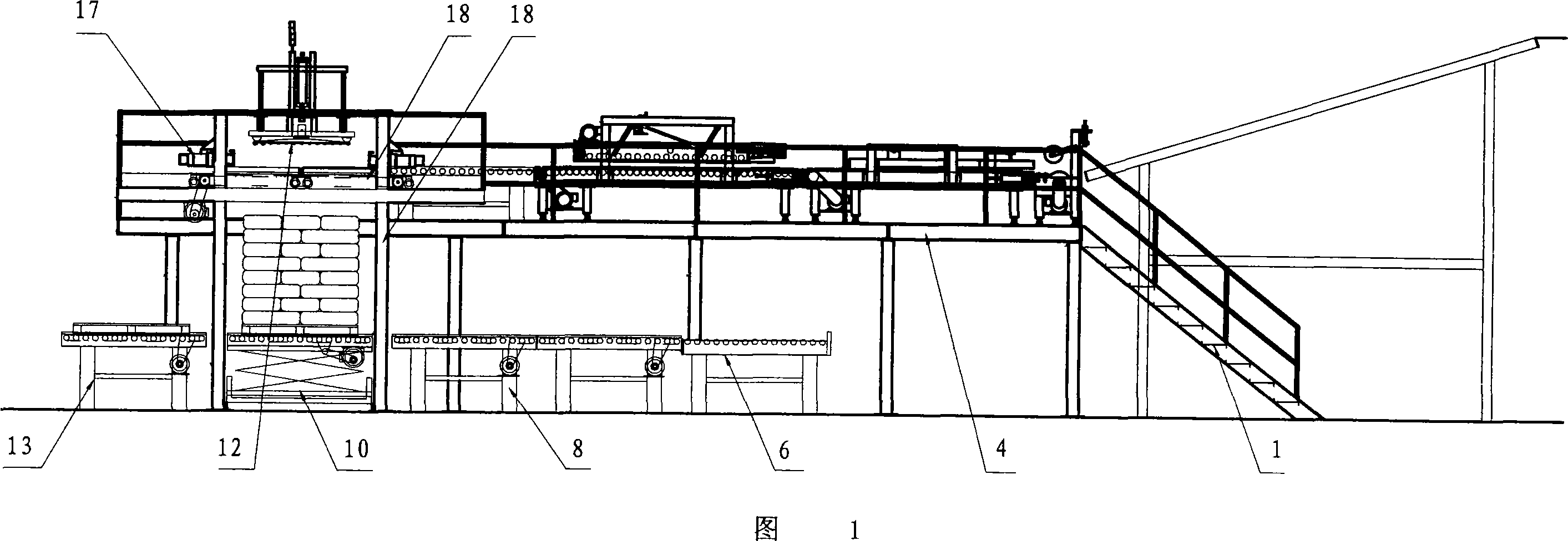
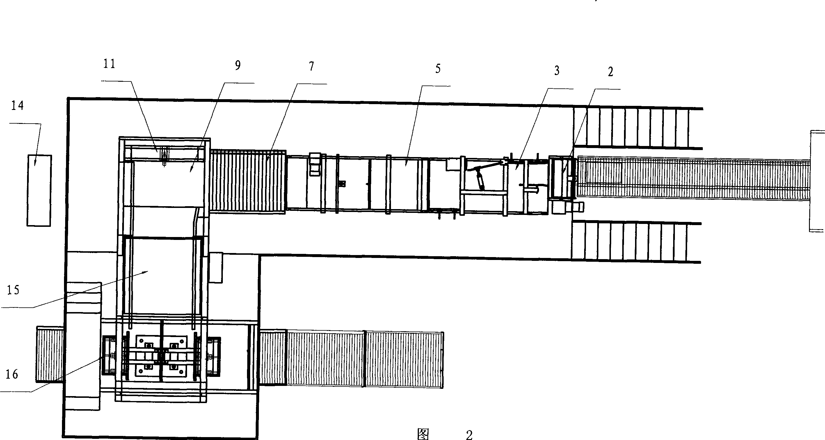
[0048] As shown in Figures 1 and 2, the utility model includes a feeding mechanism 2, a rotary bag conveying mechanism 3, a flattening conveying mechanism 5, a buffer conveying mechanism 7, a marshalling conveying mechanism 9, a marshalling pushing bag mechanism 11, and a slow stop conveying mechanism 15 , layering mechanism 16, side shaping mechanism 16, vibration shaping mechanism 12, lifting mechanism 17, pallet feeding mechanism 13, stacking and stacking mechanism 10, stacking conveying mechanism 8, pallet temporary storage conveying mechanism 6, electric Control box 14, walking platform 4 and escalator 1. The structure and function of each part are as follows:

[0049] 1. Feeding mechanism

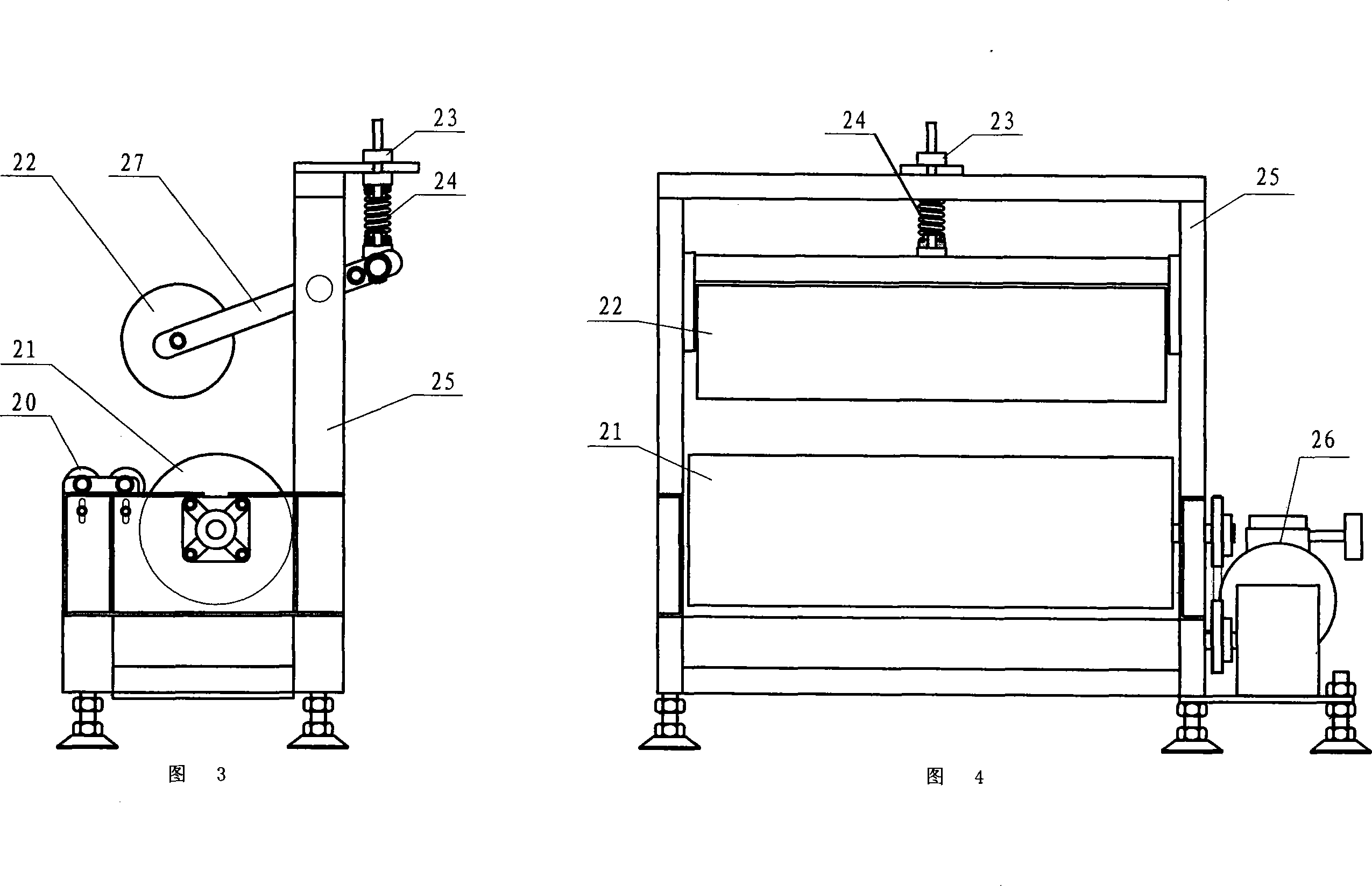
[0050] As shown in Figures 3 and 4, the feeding mechanism 2 includes a driving roller 21, a transition roller 20, a pressing roller 22, a feeding mechanism support 25, a motor and a reducer 26, and a pressing roller frame 27. Drive roller 21 is fixed by bearing and feed mechanism su...


PUM


Abstract

The invention relates to a pallet machine which can automatically pallet bagged materials as bulked cement, chemical materials, rice or the like. The invention comprises a feeder, a bag rotation transmitter, a compression transmitter, a buffer transmitter, a grouped transmitter, a grouped bag pusher, a layering machine, a side face shape corrector, a vibration shape corrector, a lifter, a disc feeder, a pallet bearing outputting device, an output transmitter, a pallet disc storage transmitter, an electric control cabinet, a walk bench, and an arm rest lift. The invention has reasonable structure, low cost, and high speed, which combines a plurality of single machines, with clear and reasonable structure and simple maintenance.

Description

technical field [0001] The utility model relates to a stacker, which is particularly suitable for automatic stacking of bagged materials such as cement, chemical raw materials, grain and other bulk materials. Background technique [0002] At present, most of the lifting parts of palletizers on the market are controlled by hydraulic pressure, and the speed is relatively slow, and the fastest can only reach 1600 bags / hour. The structure is complex, the cost is high, and it is difficult to popularize and use. Contents of the invention [0003] In order to overcome the disadvantages of the prior art, the utility model provides a palletizer, which has reasonable structural design, low cost and high speed. [0004] The technical scheme adopted by the utility model to solve its technical problems is: the utility model comprises: [0005] The active roller of the feeding mechanism is fixed with the support of the feeding mechanism through the bearing, the transition roller is hi...

Claims


Application Information

Patent Timeline
Patent Type & Authority Applications(China)
IPC IPC(8): B65G57/03B65G57/20B65G13/00B65G47/24B65G47/00B65G47/26
Inventor 李海军徐书霞刘燕勇王玉芬郭超英肖红卫李惠敏
Owner HEBEI HANGUANG HEAVY IND
Why Eureka
Try Eureka