Turbocharging device of refrigeration machine
A technology of turbocharging devices and refrigerators, which is applied to refrigerators, compressors using turbines, pump devices, etc., can solve the problems of small air transmission volume of refrigeration systems, low efficiency of refrigeration equipment, and small input power of motors, etc., to achieve Effects of reduced power consumption, increased mass, and moderate gas compression ratio
- Summary
- Abstract
- Description
- Claims
- Application Information
AI Technical Summary
Problems solved by technology
Method used
Image
Examples
Embodiment
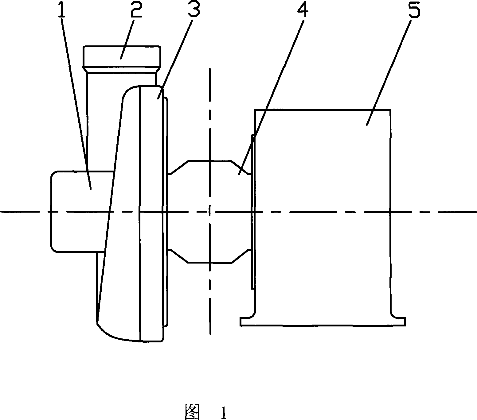
[0017] Embodiment: As shown in Figures 1 to 3, a turbocharging device for a refrigerator, the device includes an intermediate housing 4 and a low-pressure turbine part and a driving part 5 respectively located on both sides of the intermediate housing 4, the Inside the driving part 5 is also driven a turbine shaft 7 which axially passes through the intermediate casing 4 from the driving part 5 and is connected to the rotating part in the low-pressure turbine part. The turbine shaft 7 is located at the radial center of the turbocharger for the refrigerator.
[0018] The low-pressure turbine part includes a low-pressure turbine casing 3 connected to an intermediate casing 4 on one side, a low-pressure refrigerant suction port 1 located at the center of the other side of the low-pressure turbine casing 3, and a low-pressure refrigerant suction port located outside the low-pressure turbine casing 3. The diameter of the low-pressure refrigerant exhaust port 2 and the rotating part ...
specific Embodiment 1
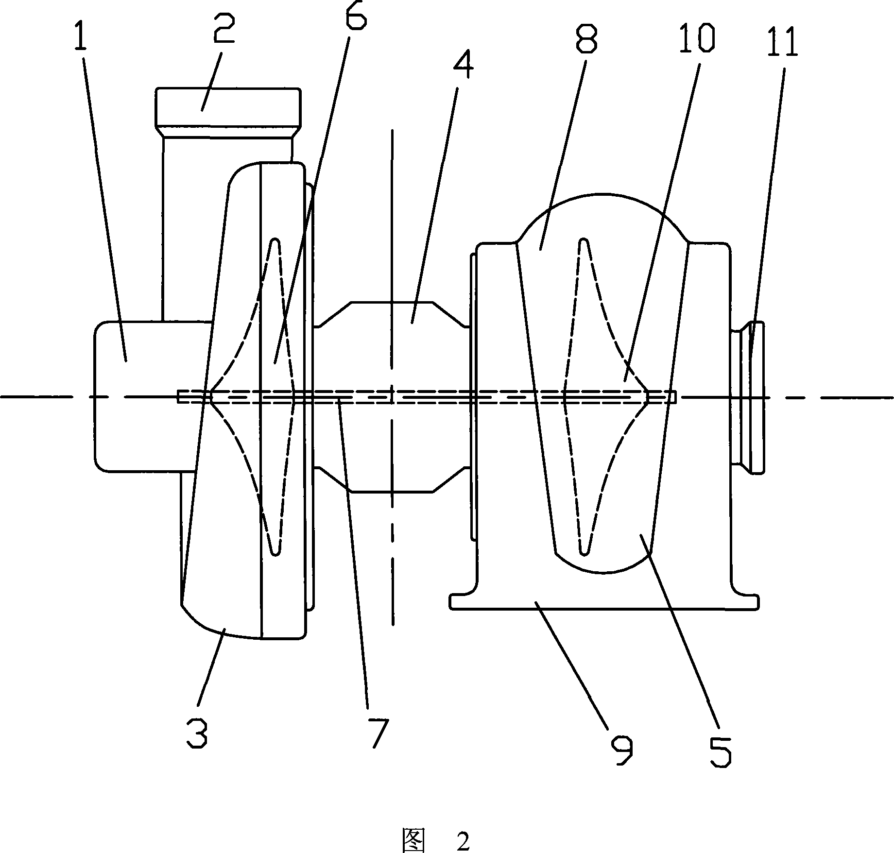
[0020] As shown in Figure 2, a turbocharging device for a refrigerating machine, the device includes an intermediate housing 4 and a low-pressure turbine part and a driving part 5 respectively located on both sides of the intermediate housing 4, and the driving part 5 also drives There is a turbine shaft 7 which passes axially from the drive part 5 through the intermediate housing 4 and is connected to the rotating part in the low-pressure turbine part. The turbine shaft 7 is located at the radial center of the turbocharger for the refrigerator.
[0021] The low-pressure turbine part includes a low-pressure turbine casing 3 connected to an intermediate casing 4 on one side, a low-pressure refrigerant suction port 1 located at the center of the other side of the low-pressure turbine casing 3, and a low-pressure refrigerant suction port located outside the low-pressure turbine casing 3. The diameter of the low-pressure refrigerant exhaust port 2 and the rotating part accurately ...
specific Embodiment 2
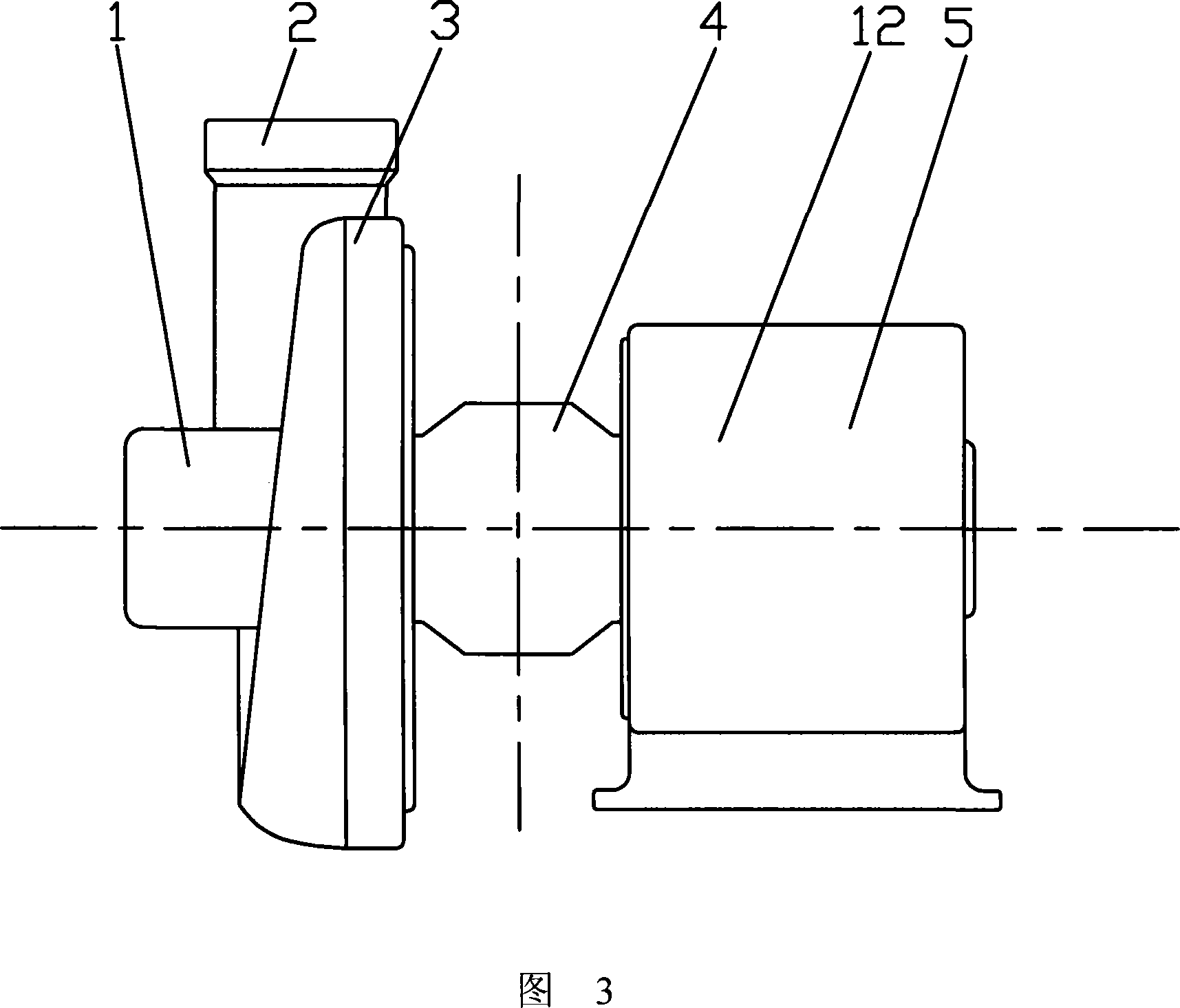
[0023] As shown in FIG. 3 , the driving part 5 in the first embodiment is replaced by a driving motor 12 , and the rotation output device of the driving motor 12 is closely connected with the turbine shaft 7 . The drive motor 12 is a common electromagnetic drive motor. The driving motor 12 drives the low-pressure turbine 6 by acting on the turbine shaft 7 inside the intermediate housing 4, and the low-pressure turbine 6 completes the high-speed delivery of the low-pressure refrigerant gas, and delivers the refrigerant to the compressor. After compression, the refrigerant gas becomes high-pressure The gas enters the system to participate in the refrigeration cycle.
[0024] The invention optimizes the circulation mode of the refrigeration system, fully utilizes the characteristics of the small compression ratio and large gas delivery volume of the turbocharger, makes up for the shortage of the small gas delivery volume of the compressor under the condition of high compression r...
PUM
 Abstract
Description
Claims
Application Information
 - R&D
- Intellectual Property
- Life Sciences
- Materials
- Tech Scout
- Unparalleled Data Quality
- Higher Quality Content
- 60% Fewer Hallucinations
Browse by: Latest US Patents, China's latest patents, Technical Efficacy Thesaurus, Application Domain, Technology Topic, Popular Technical Reports.
© 2025 PatSnap. All rights reserved.Legal|Privacy policy|Modern Slavery Act Transparency Statement|Sitemap|About US| Contact US: help@patsnap.com


