Eureka AIR delivers breakthrough ideas for toughest innovation challenges, trusted by R&D personnel around the world.

Magnetic suspension turbocharging device of refrigeration machine

A turbocharging device and magnetic levitation technology, which is applied in the direction of refrigerators, pump devices, and components of pumping devices for elastic fluids, etc., can solve the problem of small gas transmission volume in refrigeration systems, low efficiency of refrigeration equipment, and small input power of motors and other problems, to achieve the effect of reducing friction loss, eliminating the need for oil lubrication system, and moderate gas compression ratio

Inactive Publication Date: 2008-02-20
SUZHOU QUTU THERMAL CONTROL SYST
View PDF0 Cites 7 Cited by
  • Summary
  • Abstract
  • Description
  • Claims
  • Application Information

AI Technical Summary

Problems solved by technology

In this way, the refrigerant generally enters the compressor in a superheated state, and the volume of the refrigerant expands greatly, that is, the specific volume increases, so that the quality of the refrigerant that actually participates in the refrigeration cycle is relatively reduced; on the premise that the input power of the compressor is determined, the compression In order to achieve refrigeration, the machine must ensure a certain compression ratio, so the air transmission volume of the refrigeration system becomes smaller. At the same time, there is friction between the compressor shaft and the support bearing during operation, and the input power of the motor is small, and the compressor heats up. The capacity is reduced, and when the working environment of the compressor is bad, the efficiency of the refrigeration equipment is extremely low, and even cannot be used normally

Method used


Image

  • Magnetic suspension turbocharging device of refrigeration machine
  • Magnetic suspension turbocharging device of refrigeration machine
  • Magnetic suspension turbocharging device of refrigeration machine

Examples


Embodiment

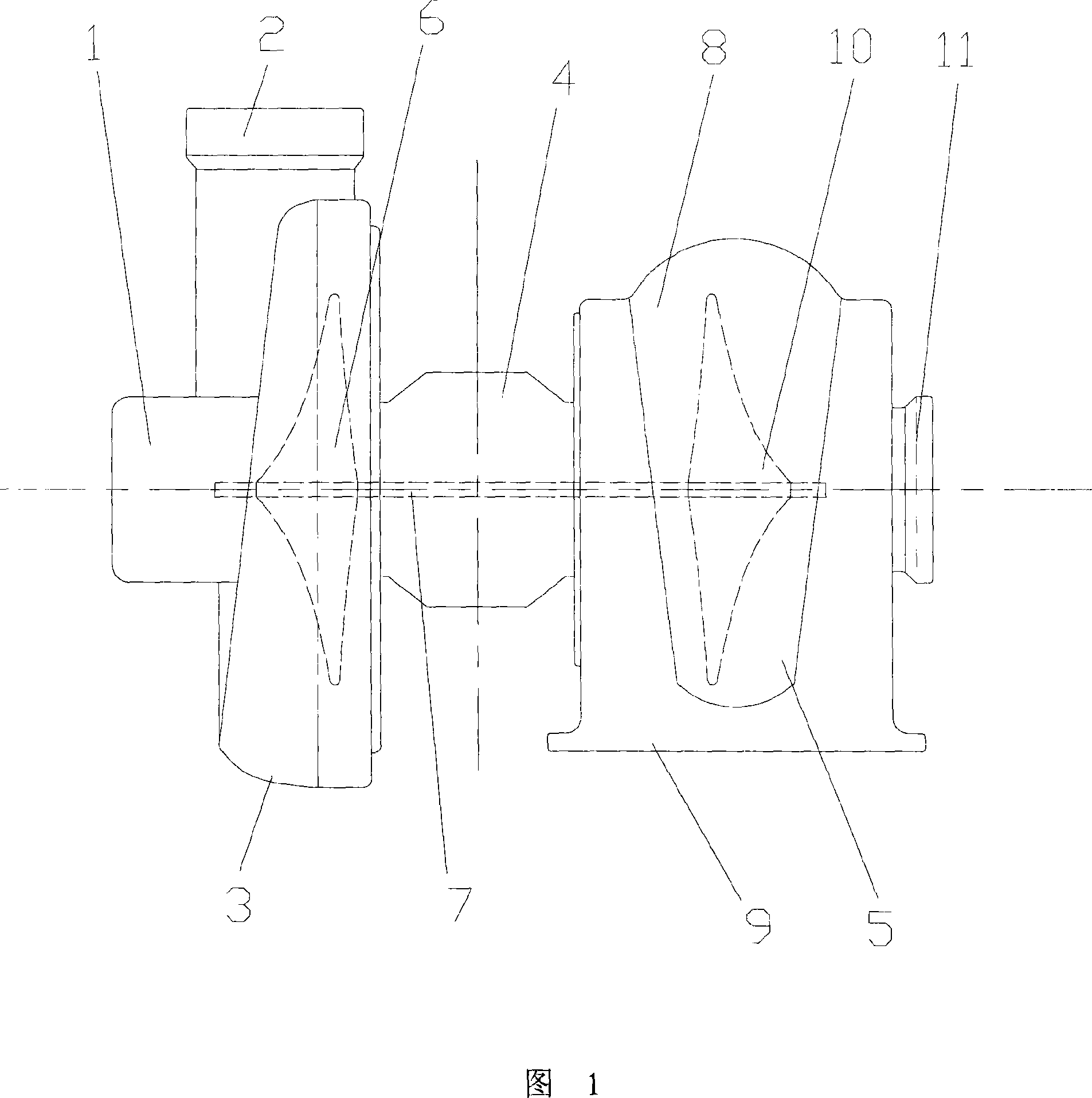
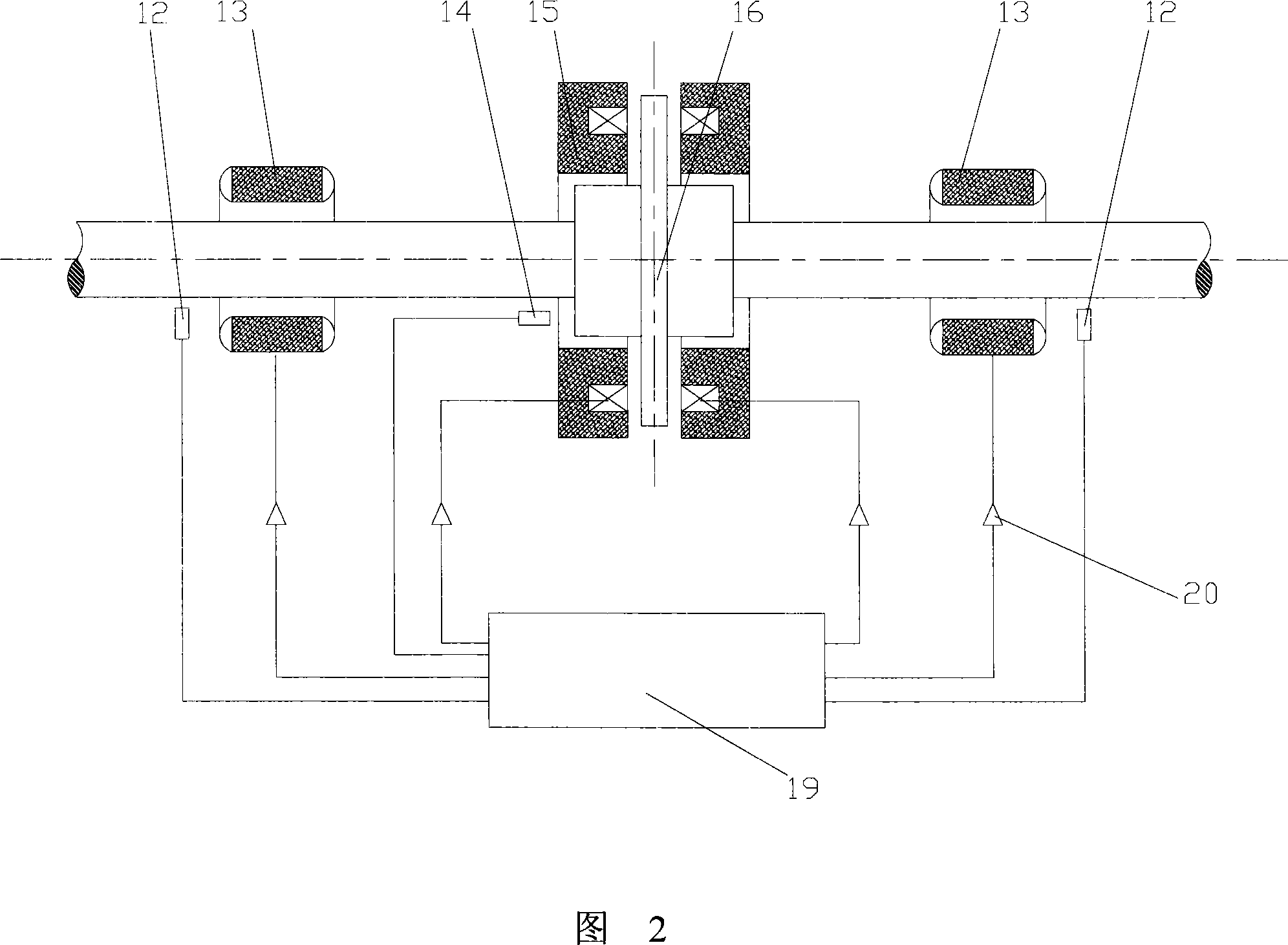
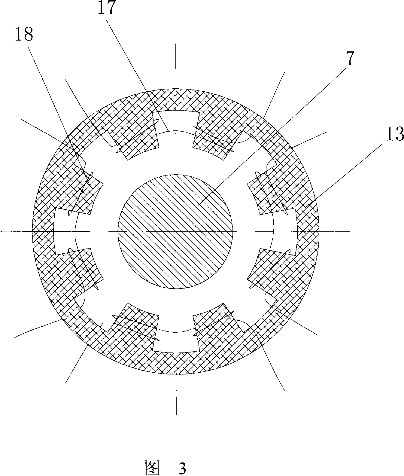
[0018] Embodiment: As shown in Figures 1 to 3, a magnetic levitation turbocharging device for a refrigerator, the turbocharging device includes a low-pressure turbine assembly, a bearing assembly 4 and a drive assembly 5, and the low-pressure turbine assembly is arranged on the bearing One side of the assembly 4, and the drive assembly 5 is located on the other side of the bearing assembly. A turbine shaft 7 is provided in the center of the inner side of the bearing assembly 4, and its axial ends extend into the inner side of the low-pressure turbine assembly and the drive assembly 5, and are connected with the low-pressure turbine assembly. The assembly is connected with the rotating part inside the drive assembly 5 . The driving assembly 5 drives the turbine shaft 7 to rotate and work, and the low-pressure turbine assembly is a radial outward flow compressor.

[0019] The low-pressure turbine assembly includes a low-pressure turbine housing 3, a low-pressure refrigerant suct...


PUM


Abstract

The invention discloses a magnetic suspension turbo charging device used on a refrigerating machine. The turbo charging device comprises a low-pressure turbine component, a bearing component and a driving component; the low-pressure turbine component is arranged at one side of the bearing component, while the driving component is arranged at the other side of the bearing component; a turboshaft is arranged at the center of the inner side of the bearing component, the two ends along the axial direction extend into the inner sides of the low-pressure turbine component and the driving component and are connected with the rotating components arranged at the inner side of the low-pressure turbine component and the driving component. By utilizing the exhaust of the refrigeration system or the drive of external force, the invention increases the air transmission quantity of the compressor, effectively increases the circulating amount of the cooling medium, reduces the running friction of the motor and improves the refrigerating output and electrical efficiency of the refrigerating machine.

Description

technical field [0001] The invention relates to a magnetic suspension turbocharging device for a refrigerator. Background technique [0002] At present, when a common vapor compression refrigerator performs a refrigeration cycle, the refrigerant evaporates and is inhaled by the compressor in a gaseous state, then enters the heat exchanger after being compressed, and then passes through a throttling device or an expander (usually a constant flow throttling mechanism) (such as capillary) mostly to achieve refrigeration) to complete the cycle. In this way, the refrigerant generally enters the compressor in a superheated state, and the volume of the refrigerant expands greatly, that is, the specific volume increases, so that the quality of the refrigerant that actually participates in the refrigeration cycle is relatively reduced; on the premise that the input power of the compressor is determined, the compression In order to achieve refrigeration, the machine must ensure a cer...

Claims


Application Information

Patent Timeline
Patent Type & Authority Applications(China)
IPC IPC(8): F04D25/04F04D29/058F25B1/053
Inventor 刘明国
Owner SUZHOU QUTU THERMAL CONTROL SYST
Why Eureka
Eureka Blog
Learn More