Electro-hydraulic proportional flow valve speed regulating control system and method

An electro-hydraulic proportional and control system technology, applied in the direction of flow control, general control system, control/regulation system, etc., can solve the speed control interference of proportional valve flow hydraulic actuator, poor spool current consistency, forward channel The problem of low control quality, etc., can reduce the adjustment amount, improve the response quality and control accuracy, and improve the quality.

Inactive Publication Date: 2008-04-30
SANY HEAVY IND CO LTD (CN)
View PDF0 Cites 39 Cited by
  • Summary
  • Abstract
  • Description
  • Claims
  • Application Information

AI Technical Summary

Problems solved by technology

[0004] Due to the influence of factors such as power supply voltage fluctuations and spool coil resistance distribution (the resistance value of a single spool coil changes with temperature, and the resistance values ​​of different spool coils are not consistent even at the same temperature), the PWM duty cycle At a certain time, the consistency of the spool current of the electro-hydraulic proportional flow valve is not good, which eventually interferes with the flow rate of the proportional valve and the speed control of the hydraulic actuator
Due to the influence of the above factors, the control quality of the forward channel of the closed-loop speed control system is not high, and a large number of adjustments need to be made on the speed feedback channel to ensure that the actual speed of the actuator follows the given speed. According to the basic theory of automatic control, the The feedback channel is highly dependent and does not use other types of compensation control methods, which will inevitably affect the dynamic response quality and static control accuracy of the control system

Method used


Image

  • Electro-hydraulic proportional flow valve speed regulating control system and method
  • Electro-hydraulic proportional flow valve speed regulating control system and method
  • Electro-hydraulic proportional flow valve speed regulating control system and method

Examples


Embodiment Construction

[0028] In order to make the above objects, features and advantages of the present invention more comprehensible, specific implementations of the present invention will be described in detail below in conjunction with the accompanying drawings.

[0029] In the following description, numerous specific details are set forth in order to provide a thorough understanding of the present invention. However, the present invention can be implemented in many ways other than those described here, and those skilled in the art can make similar extensions without departing from the connotation of the present invention. Accordingly, the invention is not limited to the specific implementations disclosed below.

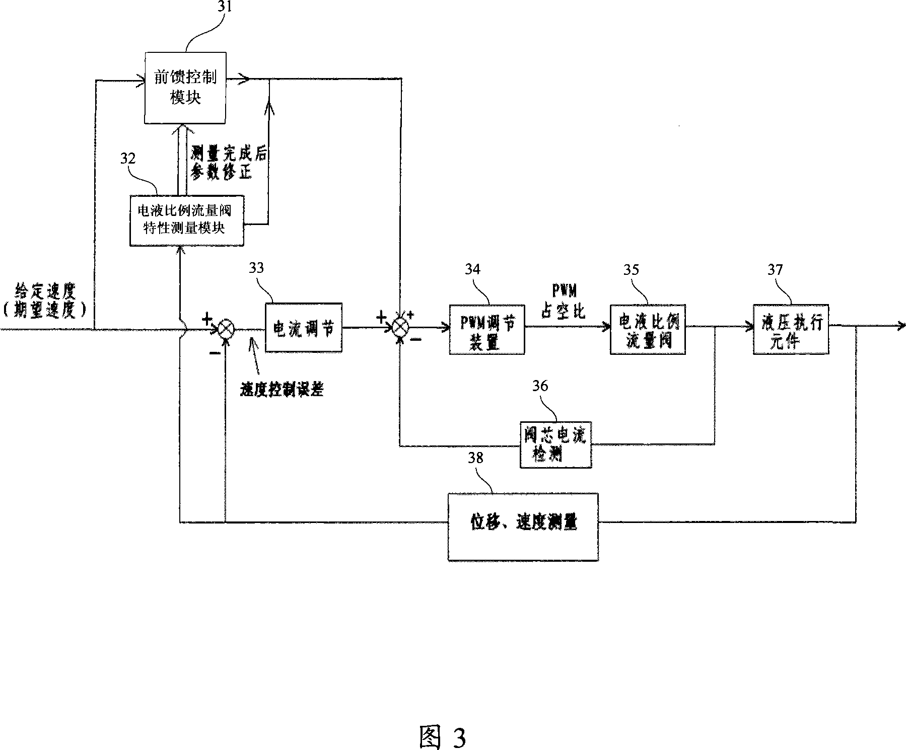
[0030] Fig. 3 is a schematic diagram of a speed regulation control system of an electro-hydraulic proportional flow valve according to a first embodiment of the present invention. As shown in Figure 3, the electro-hydraulic proportional flow valve speed regulation control system accor...


PUM


Abstract

The invention provides a timing control system and a method for an electric-hydraulic proportion flux valve. By measuring the maximum motion speed of a hydraulic executing component, and the maximum motion current and the minimum motion current of the valve core of the electric-hydraulic proportion flux valve, and by using the maximum motion speed, the maximum motion current and the minimum motion current of the valve core of the electric-hydraulic proportion flux valve, the correspondence between the movement speed of the hydraulic executing component and the current of the valve core can be obtained. By the correspondence, the valve core current corresponding to the given speed of the system can be acquired. By the valve core current corresponding to the given speed of the system, a valve core current controlling loop can be directly driven. The anticipatory speed controlling method improves the responding quality and the control precision of the forward passage of the timing control system greatly, reduces the adjusting volume of the feedback passage of the speed, and achieves the purpose of improving the quality of the closed loop control.

Description

technical field [0001] The invention relates to the technical field of hydraulic system flow control, in particular to an electro-hydraulic proportional flow valve speed regulation control system and method. Background technique [0002] The electro-hydraulic proportional flow valve is a hydraulic valve whose output is proportional to the input signal. It can continuously and proportionally control the pressure, flow and direction of the liquid flow according to the given input electrical signal. At present, in the process of using the output flow of the electro-hydraulic proportional flow valve to control the action of hydraulic actuators (including hydraulic cylinders and hydraulic motors), especially in terms of controlling the speed of hydraulic actuators, two control systems are mostly used, one control The system is an occasion that requires low speed accuracy. The control system adopts an open-loop speed control system composed of PWM adjustment technology and artifi...

Claims


Application Information

Patent Timeline
Patent Type & Authority Applications(China)
IPC IPC(8): F15B13/044F15B13/16
CPCG05B2219/42065G05B11/28G05B2219/41435G05D7/0635F15B19/002G05B13/042G05B2219/41432
Inventor 石培科唐修俊吴罕奇
Owner SANY HEAVY IND CO LTD (CN)
Why Eureka
Try Eureka