High pressure high speed rotation joint

A high-speed rotation, high-pressure technology, applied in the direction of pipes/pipe joints/fittings, adjustable connections, passing components, etc., can solve the problems of backward design structure, locking between the mandrel and the stator, etc., to achieve reasonable structure, easy maintenance, The effect of meeting technical requirements

Inactive Publication Date: 2008-04-30
韶关液压件厂有限公司
View PDF0 Cites 24 Cited by
  • Summary
  • Abstract
  • Description
  • Claims
  • Application Information

AI Technical Summary

Problems solved by technology

However, due to the outdated and backward design structure of the rotary joints produced by domestic enterprises at present, it is easy to "lock" between the mandrel and the stator due to the heat generated by the continuous operation of the rotary joint.

Method used


Image

  • High pressure high speed rotation joint

Examples


Embodiment Construction

[0012] The present invention will be further described below in conjunction with the accompanying drawings and embodiments.

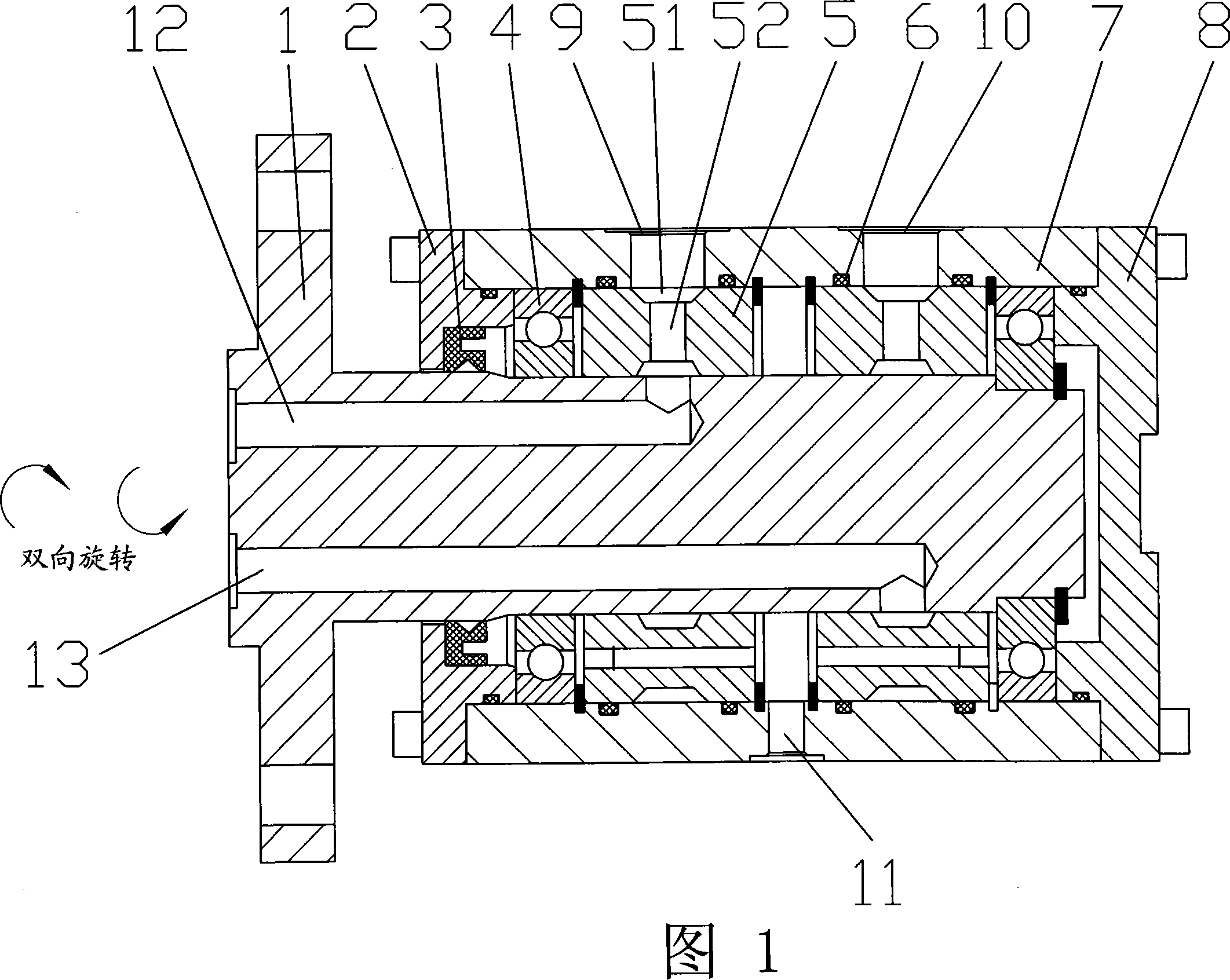
[0013] Referring to Figure 1, a high-pressure, high-speed rotary joint includes a shaft core 1 and a housing 7. The shaft 1 rotates at a high speed while the housing 7 is stationary. The shaft 1 is fixedly connected with the hydraulic cylinder and together with the main engine Rotation, a servo ring 5 is installed between the housing 7 and the mandrel 1, the servo ring 5 is controlled by the "O" ring 6 and the working pressure, the "O" ring 6 adopts a high-precision "O" ring to achieve Constant gap control and servo self-adjusting centering control, the working medium enters the working oil port A9 or working oil port B10 on the casing 1 through the pipeline, and is input and connected with the fixed casing 7 and the fixed servo ring 5. The mandrel 1 that rotates together with the main machine goes to the main machine to realize the continuous transmiss...


PUM


Abstract

The invention relates to a high-pressure high-speed rotating joint, which comprises a core shaft and a casing, wherein, the core shaft does the high-speed rotation while the casing stays still; the core shaft and a hydraulic cylinder are fixed together and rotate with a main machine; a servo ring is arranged between the casing and the core shaft; the servo ring is under the control of an O-shaped ring and the working pressure to realize constant clearance control and servo self-defined aligning control. Working medium enters a working oil opening A or a working oil opening B on the casing through a pipeline, then the working medium is input into the core shaft which does rotary movements with the main machine via the static casing and the static servo ring. In this way, continual transmission of the working medium in the rotary members is realized. The invention adopts clearance sealing technology to achieve the technological requirements of low friction and high durability, and adopts static pressure controlled clearance sealing technology to keep constant the sealed clearance and permanently prevent lock of internal structures of the rotating joint under constant pressures. The invention has the advantages of rational structure, excellent running performance and easy maintenance.

Description

【Technical field】 [0001] The invention relates to a connecting piece, in particular to a high-pressure and high-speed rotary joint with reasonable structure and good operation effect, which prevents the internal structure of the rotary joint from "locking". 【Background technique】 [0002] In almost all industrial fields, as long as there is liquid and gas medium transmission between stationary parts and rotating machines, people must use rotary joints as a connection. For example: special machine tools, deep hole drilling machines, glass machinery, etc. In the growing metallurgical industry, the use of high-pressure and high-speed rotary joints is becoming more and more extensive. Among them, the application of high-pressure and high-speed rotary joints in uncoilers on thin plate rolling mills is a classic example of the application of high-pressure, high-speed rotary joints in the metallurgical industry. However, due to the outdated and backward design structure of the rot...

Claims


Application Information

Patent Timeline
Patent Type & Authority Applications(China)
IPC IPC(8): F16L27/087
Inventor 唐建光黄志武
Owner 韶关液压件厂有限公司
Why Eureka
Try Eureka