Pre-pressure device of magnetic force pressure enforcement and micro face ultrasonic electromotor based on this device

An ultrasonic motor and pre-pressure technology, which is applied to piezoelectric effect/electrostrictive or magnetostrictive motors, generators/motors, electrical components, etc. To solve the problems of thick size and other problems, it can achieve the effect of low cost, simple pre-pressure device and thin thickness.

Inactive Publication Date: 2008-04-30
HARBIN INST OF TECH
View PDF0 Cites 8 Cited by
  • Summary
  • Abstract
  • Description
  • Claims
  • Application Information

AI Technical Summary

Problems solved by technology

[0003] The present invention solves the shortcomings of existing ultrasonic motors, such as large radial size, thick axial size, and complex stru

Method used


Image

  • Pre-pressure device of magnetic force pressure enforcement and micro face ultrasonic electromotor based on this device
  • Pre-pressure device of magnetic force pressure enforcement and micro face ultrasonic electromotor based on this device
  • Pre-pressure device of magnetic force pressure enforcement and micro face ultrasonic electromotor based on this device

Examples


Example Embodiment

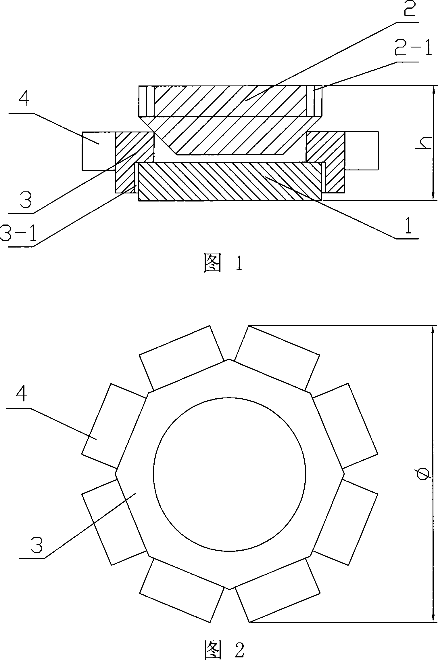
[0007] Specific embodiment 1: This embodiment will be described with reference to Figs. 1 and 2. The magnetically pressurized pre-compression device 1 of this embodiment adopts magnetic steel, and the magnetic steel is a circular sheet. The magnetic steel is a permanent magnetic material such as N35 or N42.

Example Embodiment

[0008] Embodiment 2: This embodiment will be described with reference to FIGS. 1 and 2. The difference between this embodiment and Embodiment 1 is that the thickness of the disc-shaped magnetic steel is 0.1 mm to 1 mm, and the outer diameter is 1 mm to 4 mm.

Example Embodiment

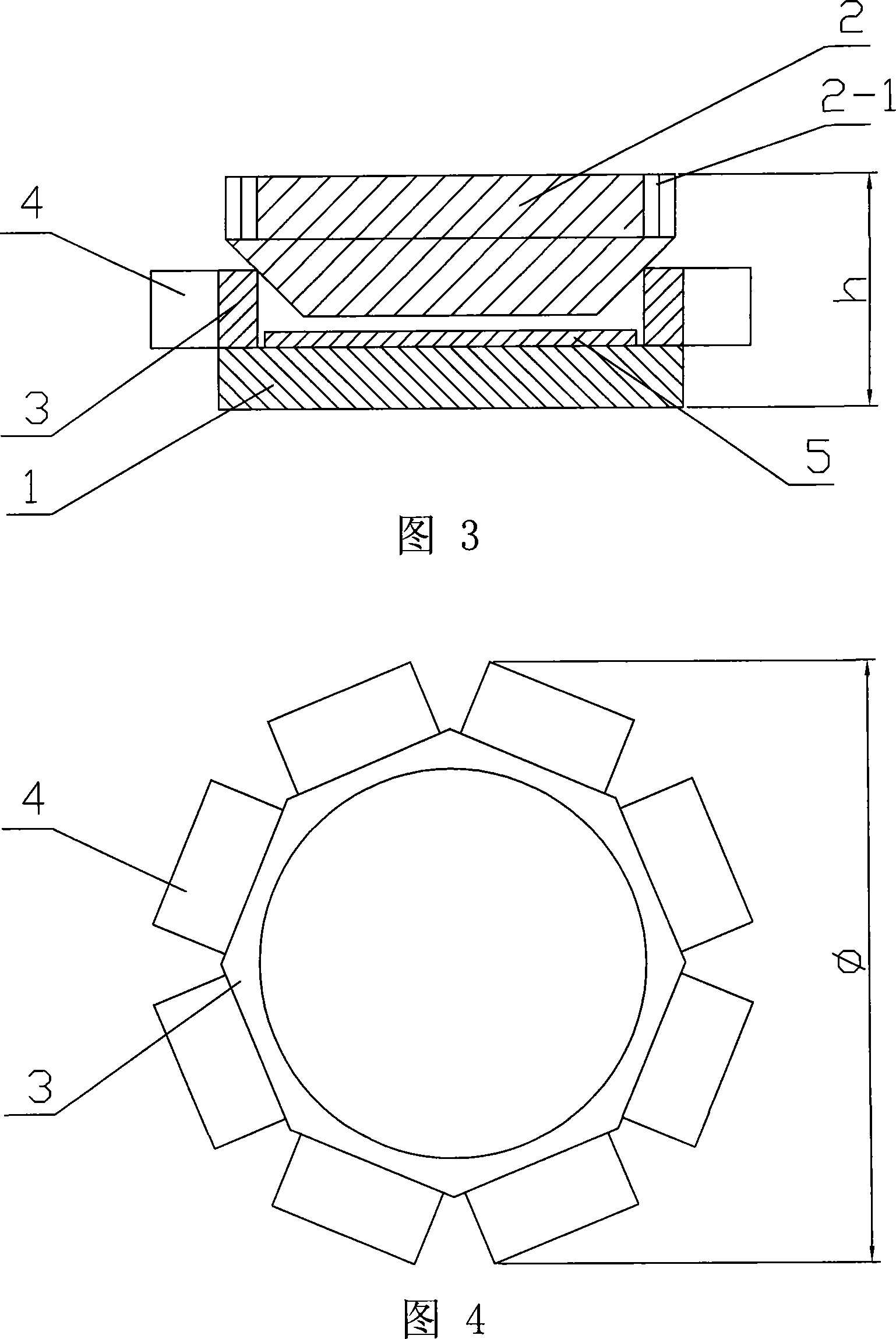
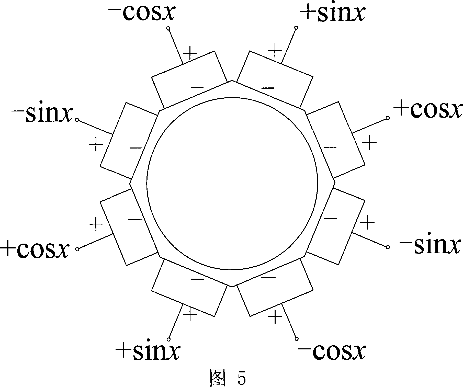
[0009] Specific embodiment three: this embodiment is described with reference to Fig. 1, Fig. 2 and Fig. 5, the miniature in-plane ultrasonic motor using the magnetic pressure pre-compression device of this embodiment is composed of a rotor 2, a stator and a magnetic pre-compression device 1 composition; the magnetically pressurized pre-compression device 1 is fixed at the bottom of the stator; the stator is composed of a metal base 3 and eight piezoelectric elements 4 of the same size, the metal base 3 is a hollow cylinder in the center of the eight Prism tube, the metal base 3 is made of a non-magnetic metal material. A piece of piezoelectric element 4 is fixed on the eight edges of the metal base 3, and four adjacent piezoelectric elements 4 of the eight piezoelectric elements 4 are One group, each group of piezoelectric elements 4 respectively apply sine wave (sin(ωt)), cosine wave (cos(ωt)), negative sine wave (-sin(ωt)), negative cosine wave (-cos(ωt)) ) Of the excitation si...


PUM

PropertyMeasurementUnit
Thicknessaaaaaaaaaa
Outer diameteraaaaaaaaaa

Abstract

The invention discloses a pre-pressure device for magnetic pressure and a miniature in-plane ultrasonic motor using the device, which relates to the field of ultrasonic motors. The invention solves the shortcomings of the existing ultrasonic motors, which are large in radial direction, thick in axial direction and complex pre-pressure device. The pre-pressure device of magnetic force pressurization of the present invention adopts magnetic steel, and magnetic steel is circular sheet, and it fixes the stator bottom; Piezoelectric elements are respectively fixed on the eight edges of the metal base. The rotor is a conical frustum of magnetically conductive material. Gears are arranged on the edge of its upper bottom surface. The side wall of the rotor is lapped on the inner edge of the metal base of the stator. The magnetic force The magnetic attraction between the pressurized pre-compression device and the rotor provides the required pre-compression between the stator and the rotor. The invention has the advantages of thin thickness, simple pre-pressure device, miniaturization of the whole machine, easy processing of piezoelectric ceramics, low cost and good controllability, and is suitable for special occasions of thinning and miniaturization.

Description

Technical field [0001] The invention relates to the field of ultrasonic motors. Background technique [0002] Ultrasonic motor is a new type of direct drive motor that uses the inverse piezoelectric effect of piezoelectric ceramics to excite ultrasonic vibration, and is driven by friction between the stator and rotor to realize the conversion of electrical energy into mechanical energy output. At present, the common ultrasonic motors mainly include traveling wave type and standing wave type, contact type and non-contact type, linear type and rotary type ultrasonic motors. However, existing ultrasonic motors generally have shortcomings such as large radial size, thick axial size, and complex loading structure. It is difficult to make it thin and the overall size is small, which cannot meet the requirements of thinning and miniaturization in special occasions. Summary of the invention [0003] The present invention solves the shortcomings of large radial size, thick axial size, an...

Claims


Application Information

Patent Timeline
IPC IPC(8): H02N2/12H02N2/14
Inventor 曲建俊田秀周宁宁程廷海
Owner HARBIN INST OF TECH
Why Eureka
Try Eureka