Cannula inserting system.

A technology of cannula and insertion direction, applied in trocars, catheters, diagnosis using light, etc., can solve the problems of inability to move and provide effective guidance, and achieve the effect of minimizing the risk of damaging the blood vessel wall

Inactive Publication Date: 2008-04-30
KONINKLIJKE PHILIPS ELECTRONICS NV
View PDF2 Cites 18 Cited by
  • Summary
  • Abstract
  • Description
  • Claims
  • Application Information

AI Technical Summary

Problems solved by technology

Also, the device cannot be moved or tilted during cannula introduction, which requires appropriate skill from the physician or medical staff
Likewise, the device

Method used


Image

  • Cannula inserting system.
  • Cannula inserting system.
  • Cannula inserting system.

Examples


Embodiment Construction

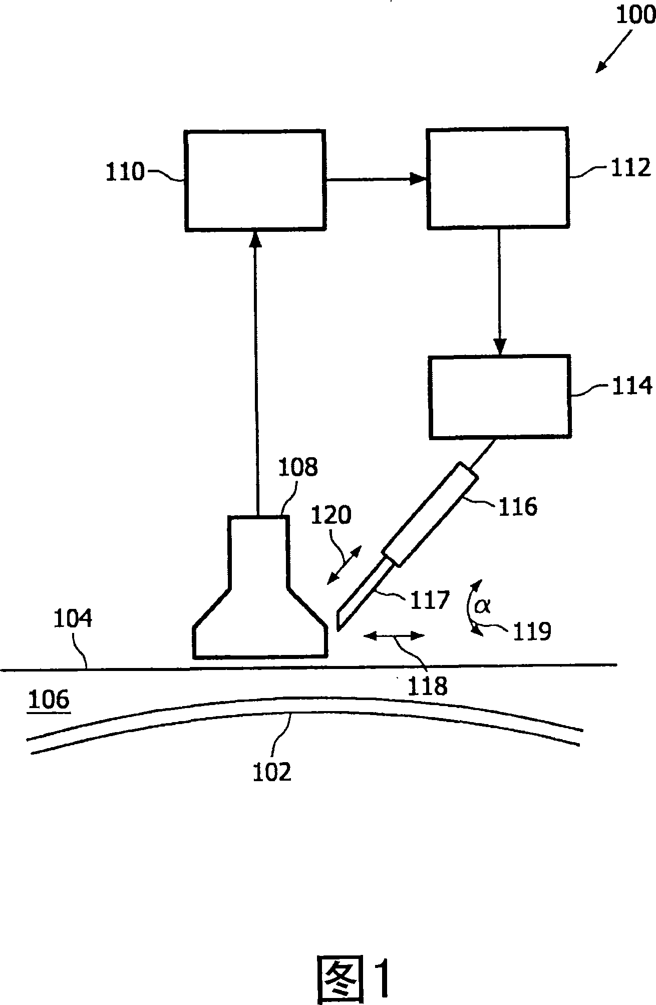
[0074]FIG. 1 shows a schematic structural diagram of a puncture system 100. The puncture system 100 has a collection module 108, a detection system 110, a control unit 112, a cannula controller 114, and a cannula carrier 116. The sleeve 117 itself may be rigidly attached to the sleeve carrier 116, which represents a sleeve insertion device for fixing the sleeve and a device for moving and aligning the sleeve 117 as controlled by the sleeve control unit 114. The cannula 117 and the cannula carrier 116 can move along the insertion direction 120 and along a direction 118 that is substantially parallel to the surface of the skin 104. In principle, the direction 118 can be any direction in a plane parallel to the skin surface. Generally, the sleeve 117 and the sleeve carrier 116 are movable in three spatial directions by means of the sleeve controller 114. Likewise, the angle α 119 between the insertion direction 120 and the surface of the skin 104 can be arbitrarily modified with the ...


PUM


Abstract

The present invention provides a highly automated puncture system for inserting a cannula or a needle into a blood vessel of a person or an animal. The puncture system has an acquisition module that allows for determining at least a location of a blood vessel underneath of the surface of a skin and is further enabled to determine an optimal puncture location that is well suitable for inserting a cannula into the blood vessel. Further, the puncture system has an actuator for moving and aligning the cannula to a determined position. The system is further adapted to autonomously insert the cannula into the blood vessel for multiple purposes, such as blood withdrawal, venous medication and infusions.

Description

Technical field [0001] The present invention relates to the field of intubation, and thus to inserting a cannula or needle into the vasculature of a human or animal. technical background [0002] Inserting a cannula or needle into the human vasculature is the daily work of a physician and needs to be performed with high precision and caution. Therefore, medical personnel need to be highly skilled in such tasks as blood drawing, drug transfusion or infusion. Physicians need to find a suitable blood vessel and introduce the distal end of the cannula or needle very precisely to prevent hematoma or exudation. Depending on the individual's vasculature, even a highly skilled and experienced doctor needs several attempts to insert the needle or cannula into the blood vessel at the appropriate position. Such multiple attempts of puncture are very painful and cause significant patient discomfort. Moreover, such multiple attempts are also quite time-consuming, which is particularly disadva...

Claims


Application Information

Patent Timeline
IPC IPC(8): A61M5/42A61B17/34A61M25/01A61M25/06
CPCA61M25/0113A61B5/1075A61B2017/3413A61M5/427A61B6/08A61B5/06A61B8/0841A61B5/0066A61B8/0833A61B5/0059A61B5/0073A61B5/0095A61B17/3403A61B5/489A61M25/06A61B5/150748A61B5/15003
Inventor N·西格林德G·吕卡森H·斯洛特C·施瓦赫F·德弗里德R·赫金伯格M·格里格斯N·艾克兰伯格
Owner KONINKLIJKE PHILIPS ELECTRONICS NV
Why Eureka
Try Eureka