Wind-guiding structure for wall type air-conditioner indoor set
A technology of air-conditioning indoor unit and air guide structure, which is applied in the direction of airflow control components, etc., can solve the problems of complex molds, increased maintenance costs, inconvenient air outlet frames, etc., and achieve simple manufacturing process, low maintenance cost, and ingenious design Effect
- Summary
- Abstract
- Description
- Claims
- Application Information
AI Technical Summary
Problems solved by technology
Method used
Image

Examples
Embodiment 1
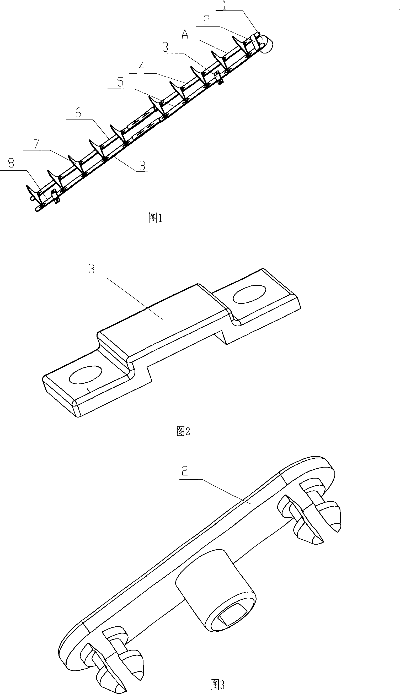
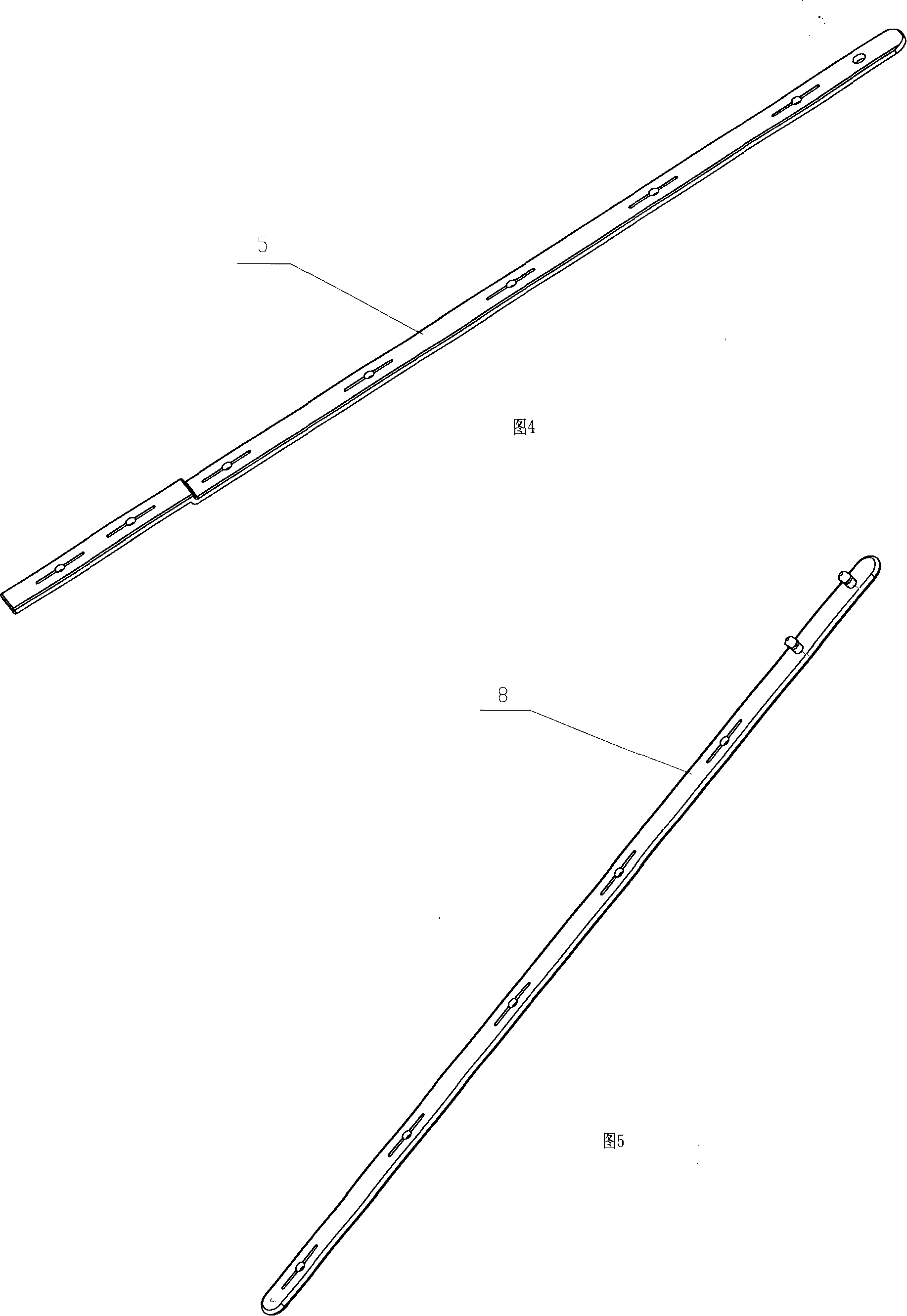
[0020] The structure schematic diagram of the present invention is shown in Figure 1, 2, 3, 4, 5, comprises motor 1 and louver 7, wherein the output shaft of motor 1 is connected with motor connecting rod 2, and the two ends of motor connecting rod 2 are respectively connected with front The louver connecting rod A and the rear louver connecting rod B are connected, and several louvers 7 are respectively connected with the front louver connecting rod A and the rear louver connecting rod B through rotating shafts. For easy disassembly, fix the motor 1 with the surface frame or air outlet frame with screws.
[0021] In this embodiment, the above-mentioned front louver link A includes a right front louver link 4 and a left front louver link 6, and the rear louver link B includes a right rear louver link 5, a left rear louver link 8, and a left front louver link 6. The left rear louver connecting rod 8 is respectively connected with the right front louver connecting rod 4 and the ...
Embodiment 2
[0027] The structure of the present invention is the same as that of Embodiment 1, the difference is that there are multiple motor connecting rods 2, and the multiple motor connecting rods 2 are respectively connected to the output shafts of a plurality of motors 1 that realize synchronous driving. The two ends of 2 are respectively connected with right front louver connecting rod 4, right rear louver connecting rod 5 and are respectively connected with left front louver connecting rod 6 and left rear louver connecting rod 8. In this embodiment, there are two motor connecting rods 2, and the two motor connecting rods 2 are respectively connected to the output shafts of the two motors 1 for synchronous driving, and the two ends of the two motor connecting rods 2 are respectively connected to the right front louver. Rod 4, right rear louver connecting rod 5 are connected and connected with left front louver connecting rod 6, left rear louver connecting rod 8 respectively.
PUM
 Abstract
Description
Claims
Application Information
 - R&D
- Intellectual Property
- Life Sciences
- Materials
- Tech Scout
- Unparalleled Data Quality
- Higher Quality Content
- 60% Fewer Hallucinations
Browse by: Latest US Patents, China's latest patents, Technical Efficacy Thesaurus, Application Domain, Technology Topic, Popular Technical Reports.
© 2025 PatSnap. All rights reserved.Legal|Privacy policy|Modern Slavery Act Transparency Statement|Sitemap|About US| Contact US: help@patsnap.com