Materials real-time detection and foreign body eliminating system based on machine vision
A real-time detection and machine vision technology, applied to instruments, computer components, character and pattern recognition, etc., to achieve the effect of improving detection efficiency, improving image quality and accuracy of material detection and foreign object recognition
- Summary
- Abstract
- Description
- Claims
- Application Information
AI Technical Summary
Problems solved by technology
Method used
Image

Examples
Embodiment 1
[0032] Example 1: Real-time detection of fruit raw materials and foreign matter removal system based on machine vision
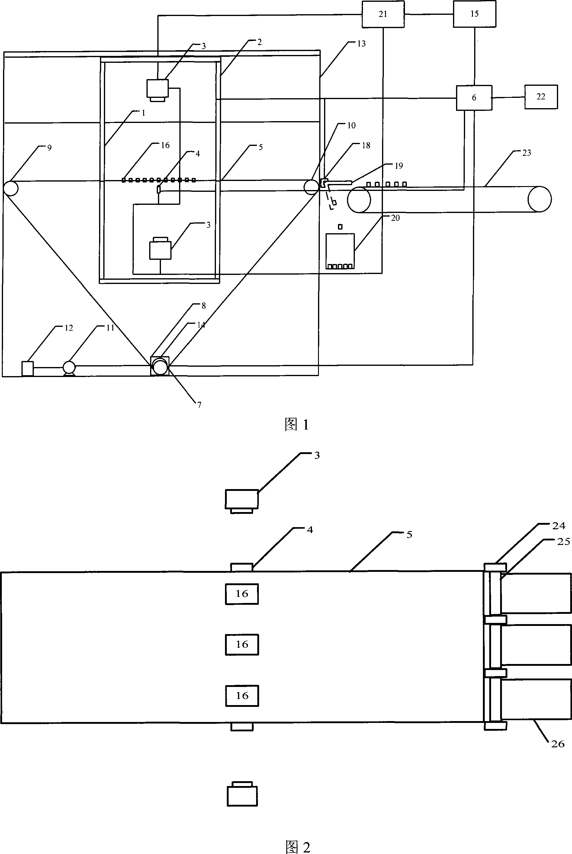
[0033] As shown in Figure 1, a machine vision-based real-time detection and foreign matter removal system for fruit raw materials includes a conveying device, a power subsystem, an optical lighting subsystem, an image acquisition subsystem, an image recognition and motion control subsystem, and a foreign matter removal subsystem. and accessories.
[0034] The conveying device includes a transmission belt 5 , rollers, a power system, an elastic coupling 7 and a rotary encoder 8 . The transmission belt 5 is a transparent transmission belt, the two ends of which are respectively wrapped around one of the driven rollers 9 and the second of the driven rollers 10. The transparent transmission belt used not only meets the requirements of food hygiene, but also can transmit light to obtain the tested fruit. The image of the bottom of the raw material can greatly im...
Embodiment 2
[0048] Example 2: Real-time detection and defect removal system for hemispherical objects based on machine vision
[0049] A machine vision-based hemisphere real-time detection and defect removal system differs from the system described in Embodiment 1 in that:
[0050] 1. The optical lighting system is composed of a dome light source illuminated from the top surface, a backlight or an LED light box illuminated from the front;
[0051] 2. The system uses cameras arranged in the upper, lower and circumferential directions to obtain images of the full area of the hemisphere. As shown in Figure 6, three area array cameras 3 in the circumferential direction are separated from each other by 120°, and are installed at the same level as the conveyor belt, and the through-beam optical fiber sensors 4 are symmetrically arranged on the sensor brackets on both sides of the conveyor belt 5; The hemispheres 17 are transported in a single row, so only one set of rejecting device is neede...
PUM
 Abstract
Description
Claims
Application Information
 - Generate Ideas
- Intellectual Property
- Life Sciences
- Materials
- Tech Scout
- Unparalleled Data Quality
- Higher Quality Content
- 60% Fewer Hallucinations
Browse by: Latest US Patents, China's latest patents, Technical Efficacy Thesaurus, Application Domain, Technology Topic, Popular Technical Reports.
© 2025 PatSnap. All rights reserved.Legal|Privacy policy|Modern Slavery Act Transparency Statement|Sitemap|About US| Contact US: help@patsnap.com