Vortex pulp distributor

A pulp distributor and pulp outlet technology, which is applied in the field of papermaking machinery, can solve the problems of pulp pressure and flow change without a good solution, poor pulp pulse adaptability, difficulty in adapting to market demand, production conditions, etc.

Inactive Publication Date: 2008-05-14
李保民
View PDF2 Cites 0 Cited by
  • Summary
  • Abstract
  • Description
  • Claims
  • Application Information

AI Technical Summary

Problems solved by technology

The defect is: the square cone header is designed and manufactured according to the calculation results of the fluid motion equation, and the slurry shrinkage loss coefficient caused by the square cone header shrinkage and the friction coefficient of the square cone header are related to the slurry flow rate, turbulent flow intensity, and slurry viscosity. The viscosity of the slurry is related to the concentration of the slurry, the temperature, the amount of chemicals and fillers, the type of fiber, and the degree of beating. These coefficients are measured in a specific experimental device, specific slurry, and temperature. The pulp distributor is difficult to adapt to industrialized large-scale production and changing market demand and production conditions
Although the present invention has a certain reduction effect on the slurry pulse, it has no good solution to the slurry pressure and flow change, and its performance needs to be further improved
In addition, the common defects of existing slurry distributors are: poor adaptability to slurry pulses, well-purified slurry must be used, and heavy and light slag removers are required, which requires a lot of equipment investment, long process, high power consumption, and land occupation. large area

Method used


Image

  • Vortex pulp distributor
  • Vortex pulp distributor

Examples


Embodiment Construction

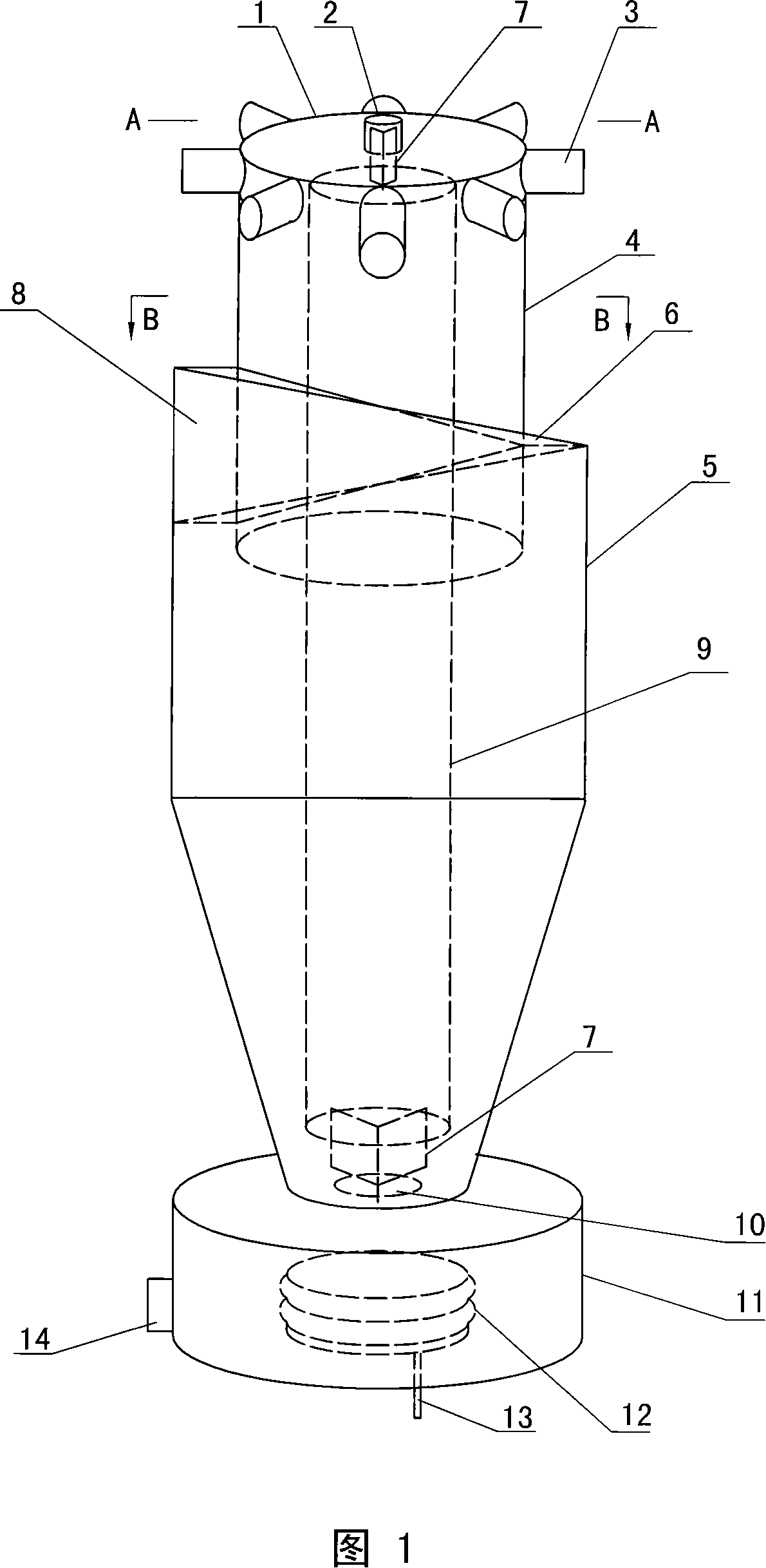
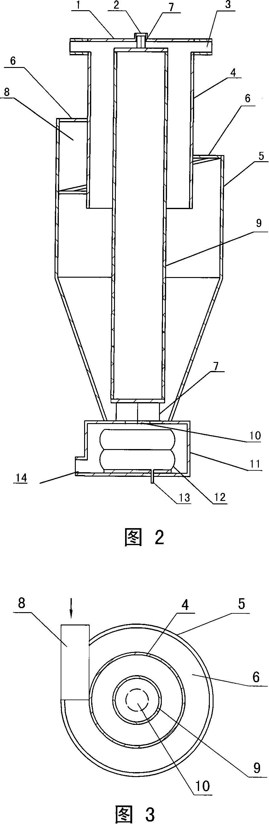
[0014] In the embodiment shown in Figures 1 to 3: the inner cylinder 4, the outer cylinder 5 and the central cylinder 9 are coaxial, the cylinder cover 1 is fixed on the top of the inner cylinder 4, and an overflow port 2 is arranged on it, and multiple pulp outlets The ports 3 are radially evenly distributed on the upper end of the inner tube 4 . The bottom of the inner cylinder 4 is horizontally open, and the outer cylinder 5 is set and fixed at the lower end of the middle part of the inner cylinder 4. The two suits form a sandwich, and the upper edge of the outer cylinder 5 is a downward spiral line, and the end of the spiral line Slightly higher than the bottom of the inner cylinder 4, the interlayer between the two cylinders is sealed by the cover plate along the helical line to form a helicoid 6, and the generation line of the helicoid 6 is perpendicular to the axis of the inner cylinder 4. The longitudinal diameter of the pulp inlet 8 is a pitch of the helix, and the hi...


PUM


Abstract

The invention provides a cyclone headbox, comprising a barrel body, a barrel cover, a pulp inlet, a plurality of pulp outlets and an overflow mouth arranged on the barrel cover. The invention is characterized in that: the barrel body comprises an internal barrel and an external barrel that are coaxial, and the barrel cover is fixed on the top end of the internal barrel; the pulp outlets are equally distributed on the upper end of the internal barrel, the external barrel is sleeved and fixed near the lower end of the middle part of the internal barrel, and an interlayer is formed between the external barrel and the internal barrel; the upper edge of the external barrel is a downward helical line, the end of which is equal or a little higher than the lower end of the internal barrel, the interlayer between the external barrel and the internal barrel is sealed into a helical surface along the helical line from a cover board; a generating line of the helical surface is vertical to an axial line of the internal barrel, and a longitudinal bore of the pulp inlet is a thread pitch of a helix; the pulp inlet is close to the tangential direction of the highest end of the helical surface and communicated with the interlayer, the bottom part of the external barrel is provided with a heavy impurity outlet, and an additional surface polished central barrel with both ends sealed is designed, while the central barrel and the internal barrel are coaxially and vertically fixed in the internal barrel. The invention has the advantage of equal pulping, eliminating the pulp pulse, no slim pulp, and good light and heavy impurities removing effect.

Description

technical field [0001] The invention relates to a swirling pulp distributor, which belongs to the technical field of papermaking machinery. Background technique [0002] All headboxes consist of three parts: a slurry distributor, a homogenizing zone and a weir plate. The slurry distributor is used to pass the slurry from the pipeline through the homogenizing zone uniformly along the width of the network, at equal pressure and at a constant speed. And weir plate, and finally transformed into a thick and uniform pulp flow covering the entire width of the paper machine, to obtain paper sheets with excellent uniformity and uniform weight. At present, there are also technical introductions about the slurry distributor in the patent documents published by the State Intellectual Property Office, such as the "equal pressure slurry distributor" with the patent number "200420043504", which is mainly composed of an inlet flange, a damping element, a cylinder, and an outlet joint. , cy...

Claims


Application Information

Patent Timeline
Patent Type & Authority Applications(China)
IPC IPC(8): D21F1/04
Inventor 李保民
Owner 李保民
Why Eureka
Try Eureka