

Method and device for power generation by employing multiple dispersed residual heat sources and various residual heat carrier medium
A technology of waste heat and carrier, which is applied in the direction of steam engine device, machine/engine, combined combustion mitigation, etc., can solve the problems of poor economy, insufficient use of waste heat, and inability to use the heat of waste heat carrier medium to generate electricity at the same time, so as to improve the overall efficiency and relatively Less heat pollution, good independence effect
- Summary
- Abstract
- Description
- Claims
- Application Information
AI Technical Summary
Problems solved by technology
Method used
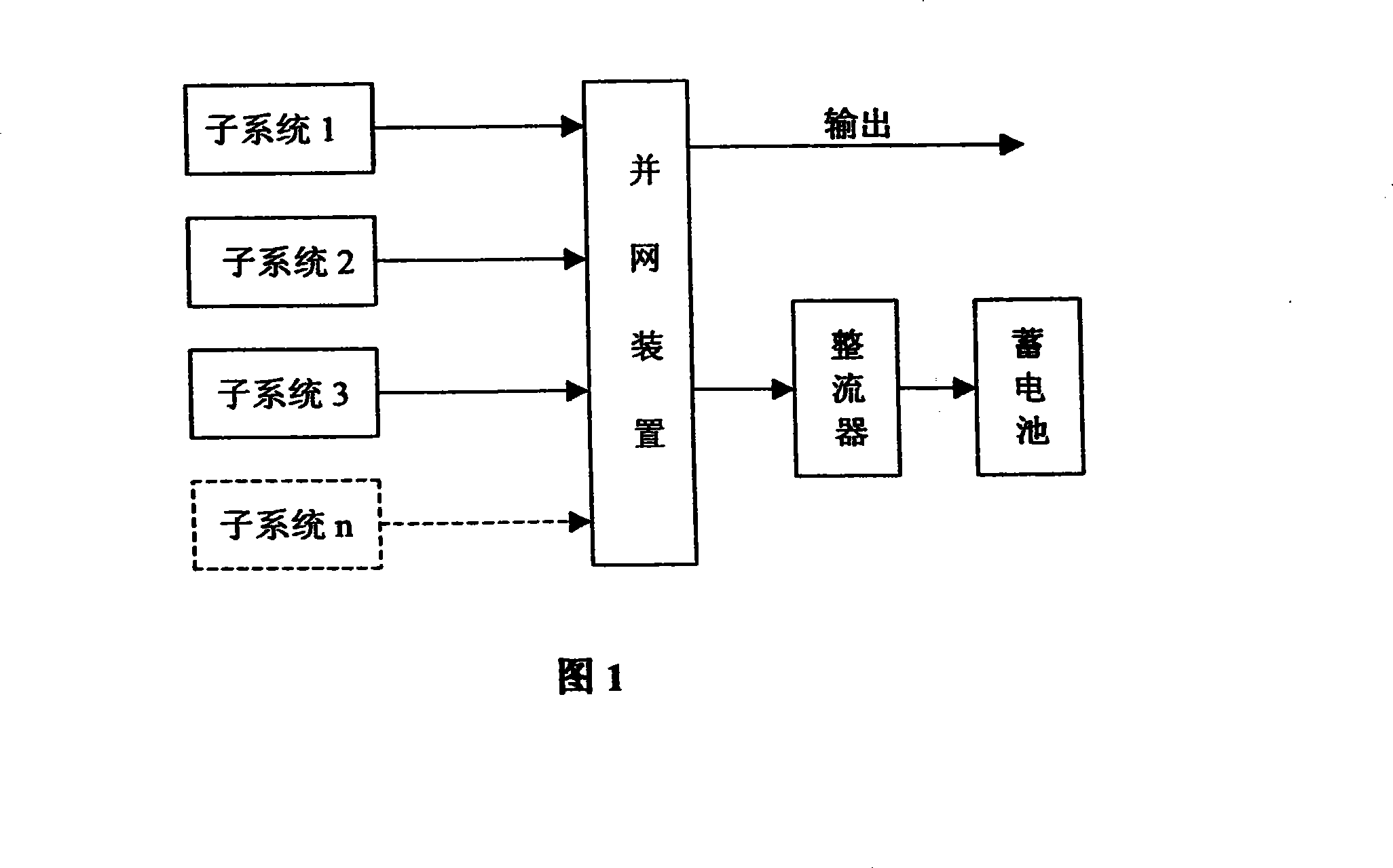
Image

Examples
example 1
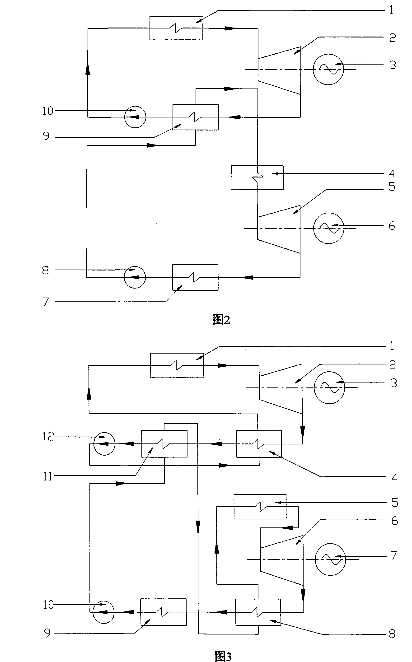
[0033] As shown in Figure 2: For the high-temperature sub-circulation system, the working medium is extracted from the gas-liquid mixer 9 by the booster pump 10, transported to the high-temperature waste heat exchanger 1, heated and vaporized, and enters the micro-high-speed turbine 2, where it expands to perform work , to push the turbine 2 to rotate, thereby driving the micro high-speed motor 3 connected with the micro high-speed turbine 2 to rotate and generate electricity. The working medium is discharged from the turbine 2 after the work is done, enters the vapor-liquid mixer 9 to condense directly, and then enters the next cycle. The cooling method of the vapor-liquid mixer can be determined according to the actual situation, which can be air cooling, water cooling or other condensation methods; in the low-temperature sub-circulation system, the working medium is extracted from the vapor-liquid mixer 7 by the booster pump 8, and then passed through the steam in the high-t...
example 2
[0035] As shown in Figure 3: the cycle working mode of this system is basically the same as that in Figure 2, the difference is that a regenerative heat exchange structure is added to the high-temperature and low-temperature sub-cycles, in which the liquid working medium is preheated by the exhaust of the turbine, specifically: for high-temperature In the sub-cycle, the exhaust gas in the micro high-speed turbine 2 will first enter the recuperation heat exchanger 4 and then enter the vapor-liquid mixer 11. After the working medium is condensed, it will enter the recuperation heat exchanger 4 through the booster pump 12, and will be pre-heated by the exhaust gas. After heating, it enters the high-temperature waste heat exchanger 1; for the low-temperature sub-cycle, the exhaust gas in the micro high-speed turbine 6 will first enter the recuperation heat exchanger 8 and then enter the vapor-liquid mixer 9, and the working fluid will be condensed and then passed through the booster...
example 3
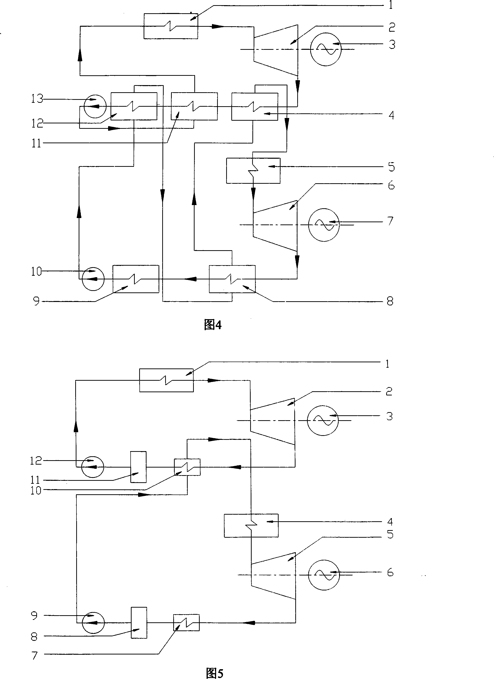
[0037]As shown in Figure 4: the working mode of this system is basically the same as that in Figure 3, the difference is that an intermediate heat exchanger is added to the high-temperature sub-cycle to preheat the working fluid from the regenerator in the low-temperature sub-cycle, specifically: For the high-temperature cycle, the exhaust gas in the micro high-speed turbine 2 enters the intermediate heat exchanger 4, then enters the recuperation heat exchanger 11, and then enters the vapor-liquid mixer 12, and enters the recuperation heat exchanger 11 through the booster pump 13 after condensation After being preheated by the exhaust gas, it enters the high-temperature waste heat exchanger 1; for the low-temperature cycle, the exhaust gas in the micro high-speed turbine 6 enters the recuperation heat exchanger 8, and then enters the vapor-liquid mixer 9, and after being condensed, passes through the booster pump 10 Enter the vapor-liquid mixer 12, then enter the recuperation h...
PUM
 Abstract
Description
Claims
Application Information